A twisted waveguide combined quasi-planar rectangular waveguide folded waveguide

A rectangular waveguide and folded waveguide technology, which is applied to waveguides, waveguide-type devices, traveling wave tubes, etc., can solve problems such as the relative bandwidth limitation of folded waveguides and traveling wave tubes, achieve electron beam energy broadening, reduce processing costs, and ensure processing accuracy Effect

Active Publication Date: 2017-11-10
北京中科航发科技发展有限公司
View PDF9 Cites 0 Cited by
  • Summary
  • Abstract
  • Description
  • Claims
  • Application Information

AI Technical Summary

Problems solved by technology

This imposes a severe limitation on the relative bandwidth of the folded waveguide TWT

Method used


Image

  • A twisted waveguide combined quasi-planar rectangular waveguide folded waveguide
  • A twisted waveguide combined quasi-planar rectangular waveguide folded waveguide
  • A twisted waveguide combined quasi-planar rectangular waveguide folded waveguide

Examples


Embodiment 1

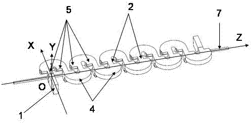
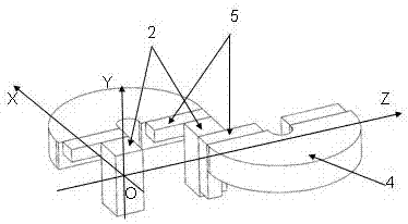
[0027] Such as Figure 1-4 shown.

[0028] A twisted waveguide combined quasi-planar rectangular waveguide folded waveguide, including at least five shortest waveguide period structures and input and output waveguides 1 sequentially connected and repeated along the Z-axis direction. Two adjacent shortest periodic waveguide structures are directly connected, and each shortest periodic waveguide structure includes at least two U-shaped bend waveguides 4 located on both sides of the YZ plane. The two U-bend waveguides 4 inside are connected by a waveguide segment structure, and one end of one U-bend waveguide 4 is connected to one end of another U-bend waveguide 4 by a waveguide segment structure, and each of the waveguide segment structures includes a The waveguide section 2 located on the Y axis and two twisted waveguide sections 5 located on both sides of the waveguide section 2 respectively, the twisted waveguide section 5 is located in the gap between the end of the U-shape...

Embodiment 2

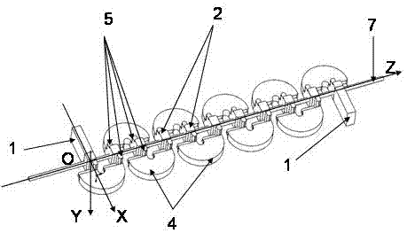
[0039] Such as Figure 5 shown.

[0040] Compared with implementation example 1, the only difference is:

[0041] All the U-bend waveguides 4 here are E-plane U-bend waveguides 4 . In each shortest waveguide periodic structure, every two twisted waveguides are directly connected to each other to form a group. The two groups of twisted waveguides are not directly connected to each other. Specifically, two adjacent shortest periodic waveguide structures are directly connected; each shortest periodic waveguide structure includes at least two U-shaped curved waveguides 4 located on both sides of the YZ plane, and the U-shaped The notch of the curved waveguide faces the YZ plane, and the two U-shaped curved waveguides 4 in the same shortest waveguide period structure are connected by a waveguide segment structure, and one end of one U-shaped curved waveguide 4 is connected to one end of the other U-shaped curved waveguide 4. The waveguide segment structures are connected, and ea...


PUM


Abstract

The invention discloses a twisted waveguide combined-type quasi planar rectangular waveguide folded waveguide, which comprises at least two shortest waveguide periodic structures communicated sequentially along a Z-axis direction and input and output waveguides. The twisted twisted waveguide combined-type quasi planar rectangular waveguide folded waveguide is composed of a plurality of U-shaped bent waveguides, twisted waveguide sections and straight waveguides. When the twisted waveguide combined-type quasi planar rectangular waveguide folded waveguide is applied to linear electromagnetic wave vacuum devices such as a traveling wave tube, in comparison with the traditional folded waveguide, the phenomenon that a 180-DEG phase difference caused by the U-shaped bent waveguides when an electron beam passes through the traditional slow wave structure is overcome, and the working bandwidth of an electromagnetic wave source can be widened more conveniently. The quasi planar structure enables all electromagnetic wave structures to be arranged on a base, a common numerical control milling machine is adopted for one-time completion, and thus, the processing precision is ensured and the processing cost is reduced. The twisted waveguide combined-type quasi planar rectangular waveguide folded waveguide can realize compact delay lines of various waveguides, single-ridge waveguides and double-ridge waveguides, particularly a slow wave structure of a compact traveling wave tube amplifier.

Description

technical field [0001] The invention relates to an electromagnetic wave transmission line. Specifically, it relates to a compact twisted waveguide combined quasi-planar rectangular waveguide folded waveguide for signal delay or slow wave structure of electromagnetic wave source. Background technique [0002] The first significant application of folded transmission lines was as a signal delay line, used for signal delay in systems such as radar. A second important application of folded transmission lines is as a slow wave structure in traveling wave tube amplifiers. At this time, the electron beam propagates along a certain straight electron channel, while the electromagnetic wave propagates along the bent transmission line. Although the phase velocity of the electromagnetic wave propagating in the bent transmission line is very fast, which can be close to the speed of light, or even greater than the speed of light, in the straight electron channel, the phase velocity of th...

Claims


Application Information

Patent Timeline
Patent Type & Authority Patents(China)
IPC IPC(8): H01J23/24H01J25/34H01P3/10H01P9/00
CPCH01J23/24H01J25/34H01P3/10H01P9/00
Inventor 王清源
Owner 北京中科航发科技发展有限公司
Why Eureka
Try Eureka