
an optical module

A technology of optical module and optical component, applied in the field of optical communication, can solve the problem of inflexible use of optical modules

Active Publication Date: 2018-08-17
HISENSE BROADBAND MULTIMEDIA TECH
View PDF4 Cites 0 Cited by
  • Summary
  • Abstract
  • Description
  • Claims
  • Application Information

AI Technical Summary

Problems solved by technology

[0008] The embodiment of the present invention provides an optical module to solve the problem of inflexible use of the optical module caused by the fixed connection relationship between the laser and the PCB board in the prior art

Method used

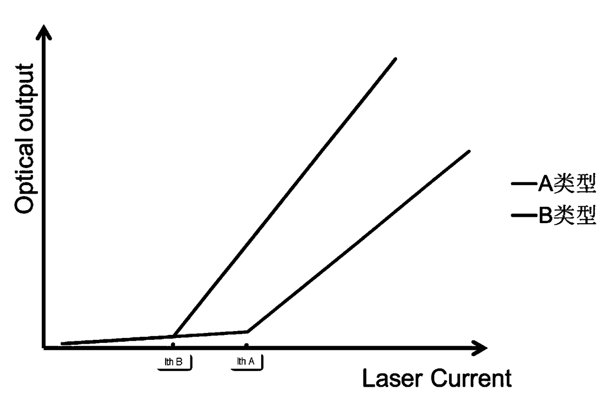
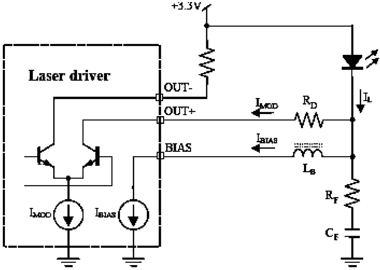
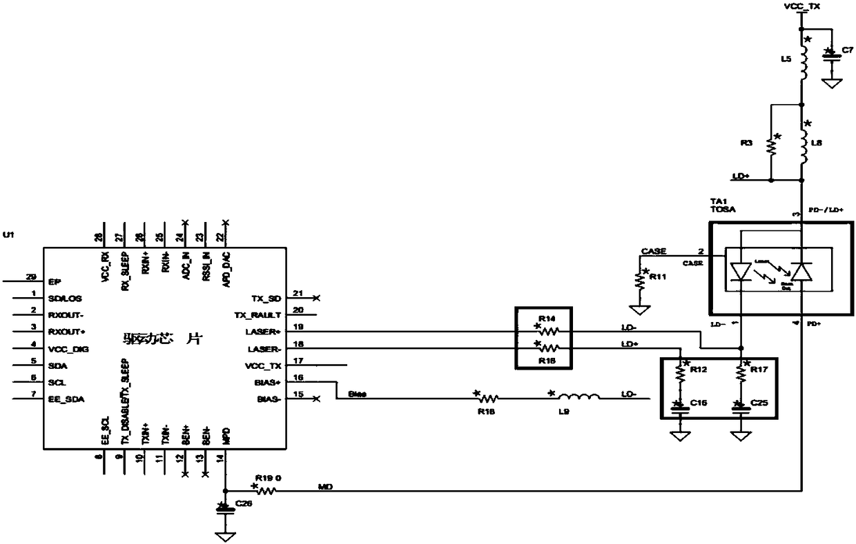

Image

  • an optical module
  • an optical module
  • an optical module

Examples


Embodiment Construction

[0024] In order to make the technical problems, technical solutions and effects solved by the present invention clearer, the preferred embodiments of the present invention will be described below in conjunction with the accompanying drawings. It should be understood that the preferred embodiments described here are only used to illustrate and explain the present invention. Invention is not intended to limit the present invention. And in the case of no conflict, the embodiments in the present application and the features in the embodiments can be combined with each other.

[0025] At present, the connection method between the laser inside the optical module and the PCB is mainly to fix the laser on the PCB by welding. This is because the driving circuit of the laser in the existing optical module is in one-to-one correspondence with the laser chip, that is, one type of laser only corresponds to one type of PCBA that provides driving current. Because the PCBA used to drive the ...


PUM


Abstract

The invention discloses an optical module, comprising a circuit board, a flexible board, and a connector for connecting the circuit board and the flexible board; the connector is fixed on the circuit board and is connected with the flexible board; An optical component, an optical chip is arranged in the optical component, and the optical chip is electrically connected with the connector through an electrical interface on the flexible board; a driving chip is arranged on the circuit board, and a driving circuit and a configurable register on the periphery of the driving circuit are arranged in the driving chip , the configurable register is used to adjust the drive current output by the drive circuit, and the drive chip provides the adjusted drive current to the optical chip through the connector. The configurable register is integrated into the driver chip to adjust the driving current of the driver circuit, making the circuit board a generalized driver circuit board. Through the connectors fixed on the circuit board, the lasers of different specifications can be flexibly replaced. Configure the configuration parameters of the register to complete the matching between the driver circuit board and the laser.

Description

technical field [0001] Embodiments of the present invention relate to the technical field of optical communication, and in particular, to an optical module. Background technique [0002] At present, the country is vigorously building a 4G high-speed communication network. The 4G high-speed network provides users with brand-new interactive entertainment methods and life experiences, and provides comprehensive services for enterprises and merchants. Whether it is the construction of the broadband China project or the development of 4G high-speed networks, the support of the optical communication industry is needed behind it. [0003] The main principle of optical fiber communication is: at the sending end, the transmitted information must first be converted into an electrical signal, and then the laser beam emitted by the optical module laser is modulated, and transmitted through the optical fiber; at the receiving end, after receiving the optical signal through the paired opt...

Claims


Application Information

Patent Timeline
Patent Type & Authority Patents(China)
IPC IPC(8): G02B6/42
CPCG02B6/4281G02B6/4284G02B6/4296
Inventor 张龙
Owner HISENSE BROADBAND MULTIMEDIA TECH
Learn More