
Automobile instrument liquid crystal display light guide plate

A technology of liquid crystal screen and light guide plate, applied in the field of light guide plate, can solve the problems affecting the use of the liquid crystal screen, uneven brightness of the light guide plate, etc., and achieve the effect of ensuring brightness, good brightness uniformity, and improving brightness

Pending Publication Date: 2016-11-16
HUANGSHAN JINMA
View PDF8 Cites 1 Cited by
  • Summary
  • Abstract
  • Description
  • Claims
  • Application Information

AI Technical Summary

Problems solved by technology

However, in the process of use, there will be a phenomenon that the brightness of the two sides of the light source is higher and the brightness of other areas is lower, that is, the brightness of the light guide plate is uneven, and there are dark bands, which will affect the use of the LCD screen.

Method used


Image

  • Automobile instrument liquid crystal display light guide plate
  • Automobile instrument liquid crystal display light guide plate
  • Automobile instrument liquid crystal display light guide plate

Examples


Embodiment 1

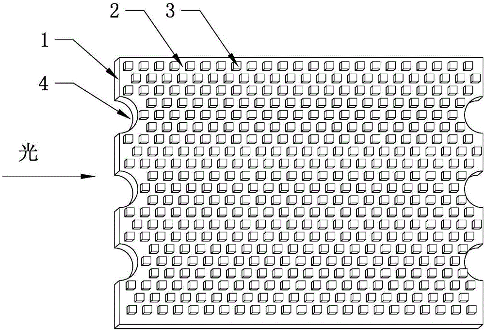
[0034] Such as figure 1 As shown, the light guide plate for vehicle instrument LCD screen includes a plate body, which is a rectangular plate with a length of 40mm, a width of 30mm, and a height of 3mm, including a light incident surface 1 where light is incident from the side and light that is emitted from the front The surface 2 and the reflective surface for reflecting light, the reflective surface is opposite to the light-emitting surface 2, and the light-emitting surface 2 is covered with multiple rows of scattering dots 3 of the same size and shape, and the scattering dots 3 of two adjacent rows are arranged alternately, and the scattering dots The shape of 3 is a square, the diameter of the circumcircle of the square is 0.2mm, and the error is within the range of ±0.1. The distance between the centers of the circumcircles of any two adjacent squares is 0.3mm. cloth, the error of the center distance is within the range of ±0.1mm, because the diameter of the circumcircle ...

Embodiment 2

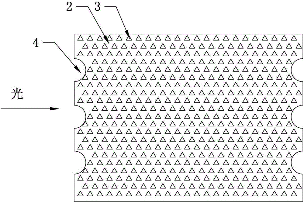
[0041] Such as figure 2 As shown, the shape of the scattering network dots 3 in the first embodiment is replaced by the technical feature that the shape of the scattering network dots 3 is an isosceles triangle, and the other technical features are the same as in the first embodiment.

[0042] The equilateral triangular scattering dots 3 make the light entering the light guide plate diffuse better through the scattering dots 3, which reduces the unevenness of the light field produced by LEDs and makes the luminance of the light guide plate more uniform.

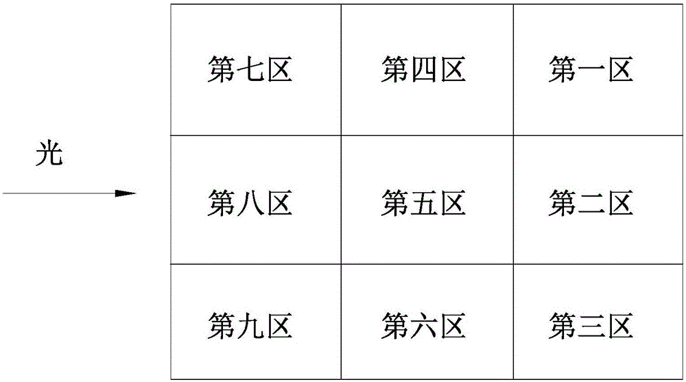
[0043] Such as image 3 As shown, the light-emitting surface 2 is divided into nine areas, which are the first area, the second area, the third area, the fourth area, the fifth area, the sixth area, the seventh area, the eighth area, and the ninth area. The light enters from the light incident surface 1 on the left. When the regular polygons are equilateral triangles, squares, regular pentagons, regular hexagons or regular ...


PUM

PropertyMeasurementUnit
Diameteraaaaaaaaaa
Lengthaaaaaaaaaa
Widthaaaaaaaaaa

Abstract

The invention discloses an automobile instrument liquid crystal display light guide plate which comprises a plate body. The plate body comprises a light entrance surface with light incident from side and a light exit surface with light emitted from the front. Rows of scattering dots with same size and shape are distributed on the light exit surface. The scattering dots of two adjacent rows are arranged alternately. The shape of the scattering dots is a regular polygon. The center distance between the circumcircles of any two adjacent regular polygons is three times of the radius of a circumscribed circle. According to the invention, the scattering dots in the shape of a regular polygon are arranged on the light guide plate; the light scattering effect of the light guide plate is greatly improved; and the light guide plate has the effect of uniform brightness.

Description

technical field [0001] The invention belongs to the field of light guide plates, and in particular relates to a light guide plate for liquid crystal screens of vehicle instruments. Background technique [0002] The basic principle of the LED backlighting of the LCD screen is to couple the light emitted by the LED light source into the light guide plate, part of the light will directly exit the surface of the light guide plate and enter the optical film, and the other part of the light will be reflected by the lower surface of the light guide plate , and then through the uniform light effect of the diffuser and the light collection effect of the prism sheet, it is transformed into a surface light source through a simple and effective optical mechanism. However, in the process of use, there will be a phenomenon that the brightness of the two sides of the light source is higher and the brightness of other regions is lower, that is, the brightness of the light guide plate is not...

Claims


Application Information

Patent Timeline
IPC IPC(8): G02B6/00
CPCG02B6/0035G02B6/0043
Inventor 庄劲松
Owner HUANGSHAN JINMA
Learn More