
Remote control nuclear phase indicator

An indicator and phase-nuclear technology, applied in the direction of phase sequence/synchronous indication, etc., can solve the problems of late power transmission time, accuracy and convenience issues, time waste, etc., and achieve improved accuracy, fewer operators, and accurate measurement Effect

Inactive Publication Date: 2016-11-16
STATE GRID SHANDONG ELECTRIC POWER CO SHOUGUANG POWER SUPPLY CO +2
View PDF9 Cites 0 Cited by
  • Summary
  • Abstract
  • Description
  • Claims
  • Application Information

AI Technical Summary

Problems solved by technology

[0005] 1. Due to the continuous increase of the pole height of the 10kV line, when the phase sequence of the line is checked once, the height of the existing insulating pole cannot meet the height requirements of the phase check, so a live work vehicle has to be used to complete the phase check of the line, resulting in electrification The workload of the work vehicle increases, and for simple nuclear phase work, it causes a waste of time and affects the rapid power transmission of the line
In some cases, due to space constraints, the live working vehicle cannot enter, and only a second verification phase can be performed, or a second verification phase can be performed after a partial line power failure. There are many problems with its accuracy and convenience.
[0006] 2. At present, most of the 10kV line phase checks are advanced high-voltage wireless phase checkers. When checking the phase sequence, two people are still required to operate and one person to supervise. It takes a long time to look up when hooking, and the workload of nuclear personnel increases
[0007] 3. The power transmission time of 10kV lines is generally late, and part of the nuclear phase work needs to be carried out at night, and the light conditions are poor. The traditional high-voltage wireless phase nuclear device cannot meet the test requirements when testing

Method used


Image

  • Remote control nuclear phase indicator
  • Remote control nuclear phase indicator
  • Remote control nuclear phase indicator

Examples


Embodiment Construction

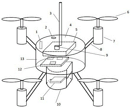
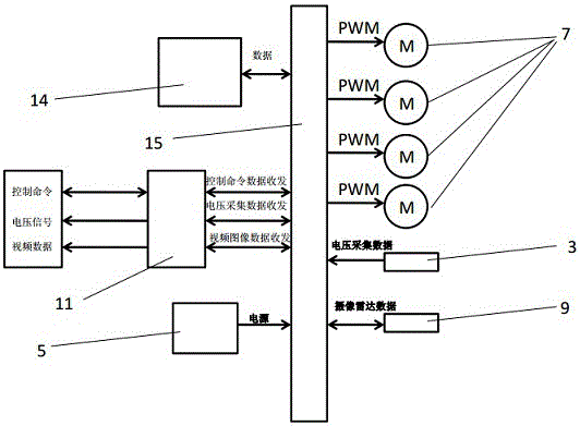
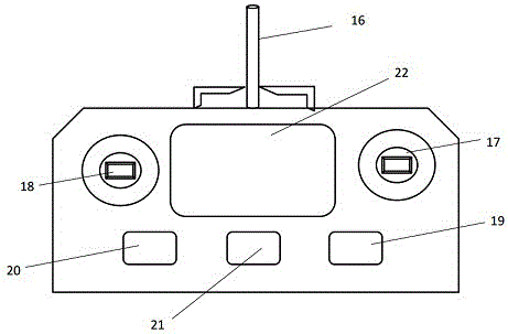
[0038] Such as figure 1 , figure 2 , image 3 , Figure 4 , Figure 5 As shown, the remote-controlled nuclear phase indicator includes a voltage acquisition aircraft device and a remote control display device. The voltage acquisition aircraft device includes two voltage acquisition aircraft, and the two voltage acquisition aircraft are respectively #1 aircraft and #2 aircraft, #1 aircraft and #2 aircraft. The structure of #2 aircraft is the same, and the remote control display device is used to control the operation of #1 aircraft and #2 aircraft.

[0039] The voltage acquisition aircraft includes a fuselage 4, four wing brackets 8 are installed on the fuselage 4, and a propeller wing 6 and a motor 7 are arranged on the wing bracket 8;

[0040] The fuselage 4 is provided with a charging interface 1, a USB interface 2 and an SD card slot 13, and the top of the fuselage 4 is provided with a voltage sensor 3 and a far-infrared wide-angle camera device 9. The inside of the fu...


PUM


Abstract

The invention discloses a remote-controlled nuclear phase indicator, which includes a voltage acquisition aircraft device and a remote control display device. The voltage acquisition aircraft device includes two voltage acquisition aircrafts, and the two voltage acquisition aircrafts are respectively #1 aircraft and #2 aircraft, # 1 aircraft and #2 aircraft have the same structure, and the remote control display device is used to control the operation of #1 aircraft and #2 aircraft; the present invention adopts the method of voltage sampling of four-axis aircraft to realize, with fewer operators, only one person is required to complete the operation , not limited by the height of the pole tower, it can realize remote control and automatic transmission and reception, so as to completely realize the "poleless" operation of the power grid nuclear phase, because the nuclear phase device uses a four-axis aircraft as the carrier technology, and the far-infrared wide-angle camera device displays the electrified distance auxiliary line , so it is not limited by light conditions, and can meet the nuclear phase requirements of the existing 10kV line.

Description

technical field [0001] The invention relates to phase verification equipment for high-voltage lines, in particular to a phase verification device for line phase sequence detection, and belongs to the technical field of phase verification for lines. Background technique [0002] With the adjustment of the network structure of the power grid, there are more new lines and renovations. At the same time, in order to improve the power supply reliability of the power grid, the number of substations, lines, and user power points is gradually increasing, resulting in an increasing number of line closure points. In the construction or maintenance of the ring network of the power system, if the AC power sources with different phases or phase sequences are paralleled or closed, a large short-circuit current will be generated, which may cause serious consequences such as line tripping, equipment damage, and even grid stability damage. , line nuclear phase work is very important. [0003...

Claims


Application Information

Patent Timeline
Patent Type & Authority Applications(China)
IPC IPC(8): G01R29/18
CPCG01R29/18
Inventor 张金峰张玉磊田兴华张涛张柄楠崔丽娟刘清源张春雷
Owner STATE GRID SHANDONG ELECTRIC POWER CO SHOUGUANG POWER SUPPLY CO
Learn More