Eureka AIR delivers breakthrough ideas for toughest innovation challenges, trusted by R&D personnel around the world.

A ball cage positioning device

A technology of positioning device and ball cage, which is applied in positioning device, workpiece clamping device, clamping and other directions, can solve the problems of high operator skill requirements, unfavorable fixture positioning, and manual operation can not meet the requirements.

Active Publication Date: 2018-06-01
ZHEJIANG KANGPURUI AUTO PARTS CO LTD
View PDF6 Cites 0 Cited by
  • Summary
  • Abstract
  • Description
  • Claims
  • Application Information

AI Technical Summary

Problems solved by technology

[0003] The ball cage, that is, the universal joint cage, needs to be positioned better during the production and processing process. However, due to the unique shape and structure of the ball cage, it is not conducive to the positioning of the universal fixture. The clamping mainly depends on the manual clamping of the operator, which requires high skills of the operator, especially when the position of the ball cage needs to be adjusted frequently in order to realize the processing of different parts of the ball cage, and manual operation cannot satisfy Require

Method used


Image

  • A ball cage positioning device
  • A ball cage positioning device
  • A ball cage positioning device

Examples


Embodiment Construction

[0019] The following are specific examples of the present invention to further describe the technical solutions of the present invention, but the present invention is not limited to these examples.

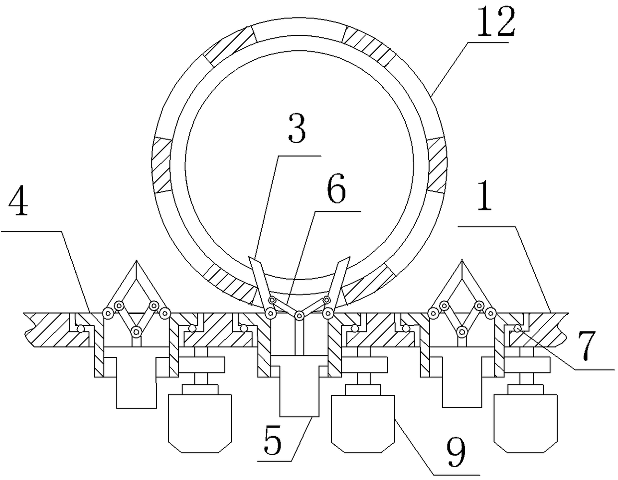
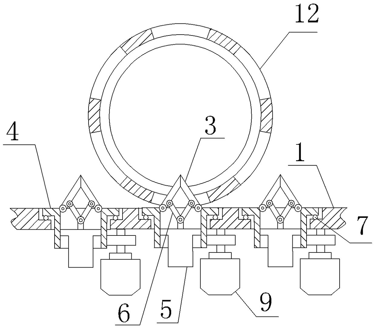
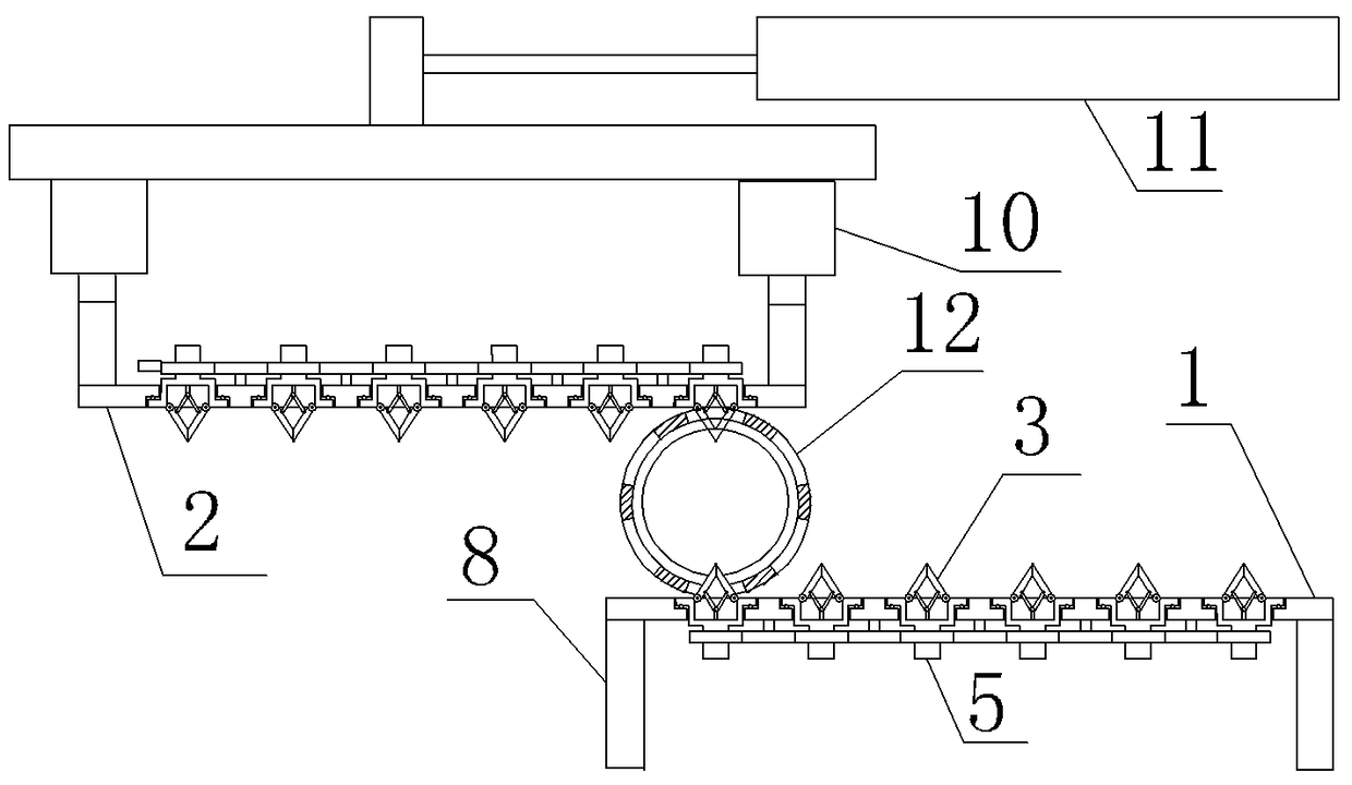
[0020] As shown in the figure, a ball cage positioning device includes a lower guide plate 1 and an upper guide plate 2 for supporting and guiding the ball cage. Six ball cage azimuth controllers are arranged along the length direction of the guide plate, and the spacing between the ball cage azimuth controllers is equal to the circumferential spacing of the 12 cage windows. The cage orientation controller includes two opening and closing plates 3 that can extend into the window of the ball cage. The bottom ends of the two opening and closing plates are connected to the rotating drum 4 through column hinges, and the rotating drum axis is perpendicular to the guide plate. Two opening and closing plates are arranged opposite to each other in the length direction of the guide plate, ...


PUM


Abstract

The invention provides a locating device for constant-velocity universal joints, and belongs to the technical field of work-piece locating. The locating device solves the problem that the constant-velocity universal joints cannot be held or located by universal clamps in the prior art. The locating device for the constant-velocity universal joints comprises a lower guide plate and an upper guide plate; a plurality of constant-velocity universal joint direction controllers are arranged in the length directions of the guide plates, the distance between every two constant-velocity universal joint direction controllers is an integral multiple of the circumferential distance of windows on the constant-velocity universal joints, and each constant-velocity universal joint direction controller comprises two opening-closing plates capable of extending into the constant-velocity universal joint windows; rotary drums are arranged on the guide plates in a rotating mode, the guide plates are provided with rotation control mechanisms controlling the rotary drums to rotate relative to the guide plates, and the upper end faces of the rotary drums are flush with the surfaces of the guide plates; and the upper guide plate is provided with a mechanism controlling lifting and horizontal moving of the upper guide plate. According to the structural feature that the constant-velocity universal joints are provided with the constant-velocity universal joint windows, the constant-velocity universal joints can be held and located, multi-angle adjustment of the constant-velocity universal joints can be realized, and therefore the machining requirements can be met.

Description

technical field [0001] The invention belongs to the technical field of workpiece positioning, and relates to a positioning device, in particular to a ball cage positioning device. Background technique [0002] With the rapid development of the automobile industry, constant velocity universal joints occupy an important position in the automotive drive shaft industry with its unique constant angular velocity torque transmission and superior mechanical properties, and the quality of constant velocity universal joints is even more important. It is related to the performance and life of the product. [0003] The ball cage, that is, the universal joint cage, needs to be positioned better during the production and processing process. However, due to the unique shape and structure of the ball cage, it is not conducive to the positioning of the universal fixture. The clamping mainly depends on the manual clamping of the operator, which requires high skills of the operator, especiall...

Claims


Application Information

Patent Timeline
Patent Type & Authority Patents(China)
IPC IPC(8): B23Q3/18B25B11/00
CPCB23Q3/18B25B11/00
Inventor 郑枫朱明杰姚东杰陆超杰
Owner ZHEJIANG KANGPURUI AUTO PARTS CO LTD
Why Eureka
Eureka Blog
Learn More