
Clamping tool

A technology for clamping tooling and clamping parts, which is applied in the field of clamping tooling, can solve problems such as low work efficiency, and achieve the effect of improving efficiency, saving time for tooling replacement, and better clamping workpieces

Active Publication Date: 2016-11-16
ZHENGZHOU YUTONG BUS CO LTD
View PDF8 Cites 2 Cited by
  • Summary
  • Abstract
  • Description
  • Claims
  • Application Information

AI Technical Summary

Problems solved by technology

[0004] The object of the present invention is to provide a clamping tool to solve the problem of low work efficiency when the existing clamps clamp the workpiece

Method used


Image

  • Clamping tool
  • Clamping tool
  • Clamping tool

Examples


Embodiment Construction

[0022] Embodiments of the present invention will be further described below in conjunction with the accompanying drawings.

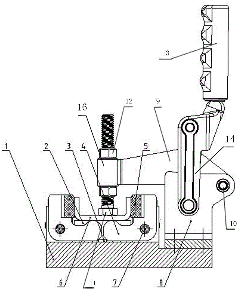
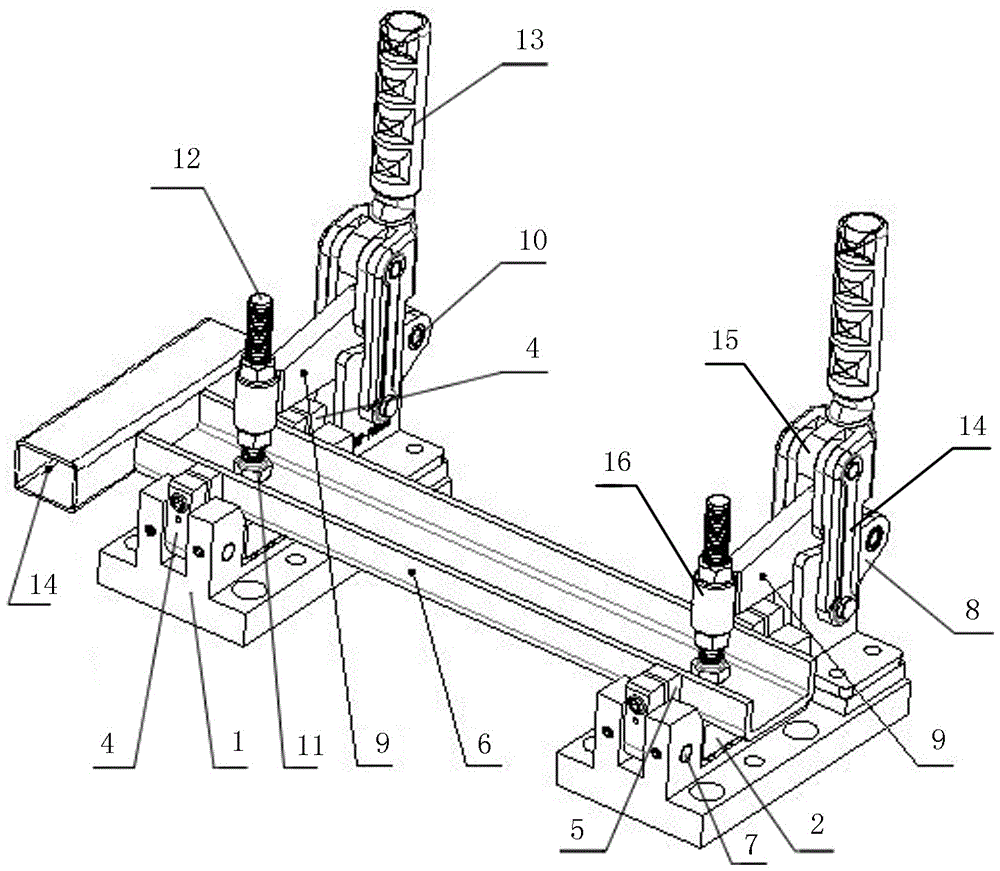
[0023] A specific embodiment of a clamping device of the present invention, such as Figure 2 to Figure 3 As shown, including the base 1, a pair of L-shaped crank arms 4 are arranged on the left side of the base 1, and the two L-shaped crank arms 4 are symmetrically distributed, and are hingedly connected to the base 1 through the first pin shaft 7 respectively, and the L-shaped crank arms 4 The supporting edge above is a clamping part that contacts and cooperates with the side of the workpiece 6, and the supporting edge below the L-shaped crank arm 4 is a supporting part that supports and cooperates with the bottom surface of the workpiece 6. The clamping parts on the two L-shaped crank arms 4 Elastic pads 5 made of polyurethane material are respectively provided on the top, and the ends of the support parts on the two L-shaped crank arms 4 are respecti...


PUM


Abstract

The invention relates to a clamping tool. The clamping tool comprises two chucks which are arranged in opposite directions; each chuck is provided with an elastic pressing unit; and each elastic pressing unit is provided with workpiece jacking and pushing faces arranged in opposite directions. Compared with the prior art, when the tool is used for clamping a workpiece large in contour size difference, elastic deformation of elastic components can absorb and compensate for the error of the contour precision of the workpiece, the workpiece can be better clamped, and the work efficiency is improved.

Description

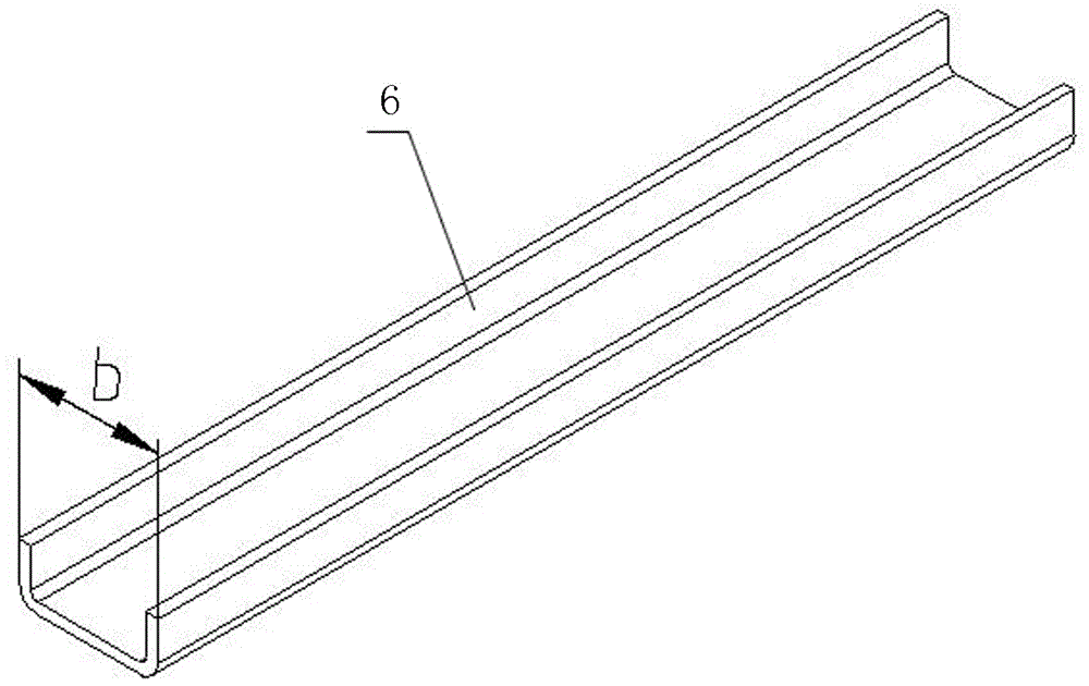
technical field [0001] The invention relates to a clamping tool. Background technique [0002] At present, robot welding technology has been widely used in the welding of bus frame. Because seat channel steel is generally made of thick plate rolls, limited by the processing technology, the processed channel steel often has the following problems: (1) It is difficult to guarantee the contour accuracy of the parts, especially the width dimension b of the channel steel, such as figure 1 (2) The product consistency is not good. [0003] However, when robot welding technology is used to weld the bus frame, the welded parts are required to meet relatively precise positioning accuracy, but the existence of the above problems has caused great difficulties in the design and use of welding fixtures. If the existing fixtures, fixtures One of the two clamps on the upper is fixed, and the other clamping head can be rotated by adjusting the bolt relative to the fixed clamping head; when...

Claims


Application Information

Patent Timeline
IPC IPC(8): B23K37/04B23K101/24
CPCB23K37/0443B23K2101/24
Inventor 马振强谢群鹏
Owner ZHENGZHOU YUTONG BUS CO LTD
Learn More