Artificial knee joint prosthesis
A technology of artificial knee joints and prostheses, applied in the direction of knee joints, prostheses, elbow joints, etc., can solve the problems of unreproducible, short life of prosthesis, and dissatisfied patients with postoperative functions, so as to achieve unsatisfactory functions and use long life effect
- Summary
- Abstract
- Description
- Claims
- Application Information
AI Technical Summary
Problems solved by technology
Method used
Image
Examples
Embodiment 1
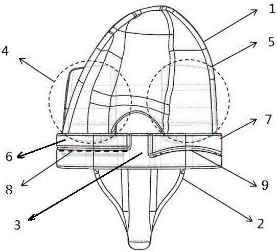
[0024] This embodiment provides an artificial knee joint prosthesis, combined with figure 1 As shown, it includes a femoral prosthesis 1 and a tibial prosthesis 2. The upper end of the tibial prosthesis 2 is provided with a tibial metal bracket 3, and the lower end of the femoral prosthesis 1 is associated with the tibial metal bracket 3 to form a joint.
[0025] The artificial knee joint prosthesis provided in this embodiment mainly realizes the physiological kinematics of "the medial condyle pivots and the lateral condyle rolls back" through the movement of the femoral prosthesis 1 in the tibial metal bracket 3. In addition to the flexion and extension activities between the femoral prosthesis 1 and the tibial prosthesis 2, it can also be accompanied by the physiological forward and backward sliding and internal and external rotation of the femoral articular surface on the tibial articular surface, providing patients with more natural knee joint function.
Embodiment 2
[0027] This embodiment further describes the structure between the femoral prosthesis 1 and the tibial prosthesis 2, from figure 1 It can be seen that the lower end of the femoral prosthesis 1 is provided with a medial condyle 4 and a lateral condyle 5 of a spherical structure, and the medial condyle 4 and the lateral condyle 5 form joints with the tibial metal tray 3 in a spherically associated manner.
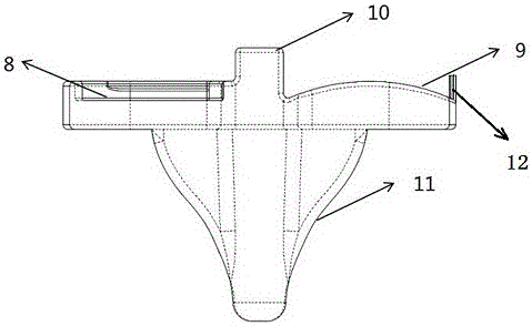
[0028] The inner polyethylene liner 6 and the outer polyethylene liner 7 are respectively installed on the tibial metal bracket 3, and the medial condyle 4 and the lateral condyle 5 at the lower end of the femoral prosthesis 1 pass through the inner polyethylene liner 6 and the outer polyethylene liner 7 respectively. Installed on the tibial metal support 3.
[0029] Such as image 3 As shown, the upper surface of the inner polyethylene liner 6 is concave spherical, and is associated with the spherical surface of the medial femoral condyle 4 to form a ball-and-socket joint, ...
Embodiment 3
[0032] This implementation is further described on the basis of Embodiment 2. In this embodiment, in order to better realize the function, the upper surface of the inner polyethylene liner 6 is spherical, and is associated with the medial femoral condyle 4 to form a joint. The relationship between the polyethylene liner 6 and the radius of the medial femoral condyle 4 is divided into a fully restricted type and a semi-restricted type.
[0033] Completely restrictive type: that is, the spherical radius of the upper surface of the medial polyethylene liner 6 = the radius of the medial femoral condyle. In this type, the medial polyethylene liner 6 and the medial femoral condyle 4 are completely fitted and mutually restricted, and no deviation will occur , of course, can precisely satisfy the various functions of the knee joint.
[0034] Semi-restricted type: that is, the spherical radius of the upper surface of the inner polyethylene liner 6 is greater than the radius of the medi...
PUM
 Abstract
Description
Claims
Application Information
 - R&D
- Intellectual Property
- Life Sciences
- Materials
- Tech Scout
- Unparalleled Data Quality
- Higher Quality Content
- 60% Fewer Hallucinations
Browse by: Latest US Patents, China's latest patents, Technical Efficacy Thesaurus, Application Domain, Technology Topic, Popular Technical Reports.
© 2025 PatSnap. All rights reserved.Legal|Privacy policy|Modern Slavery Act Transparency Statement|Sitemap|About US| Contact US: help@patsnap.com


