
Special pressure head for cylinder hydrostatic test

A hydraulic test and indenter technology, which is applied in the direction of applying stable tension/pressure to test the strength of materials, etc., can solve the problems that it is difficult to meet the automatic operation of the automated test production line, the indenter cannot meet the use requirements, and the connection and sealing cannot be realized. , to achieve the effect of reliable sealing, avoid bearing axial force, simple and compact structure

Active Publication Date: 2019-05-31
无锡昌华机电制造有限公司
View PDF8 Cites 0 Cited by
  • Summary
  • Abstract
  • Description
  • Claims
  • Application Information

AI Technical Summary

Problems solved by technology

The above-mentioned connection and sealing method of the hydraulic test pressure head requires the operator to manually screw in. The entire operation process is cumbersome, the labor intensity of the workers is high, and the efficiency of the test operation is low. It is difficult to meet the needs of the automatic operation of the automated test production line, and , the above-mentioned connection and sealing method will generate additional axial force on the inlet and outlet of the pressure gas cylinder. For the pressure gas cylinder that is not allowed to bear the axial force in the pressurization test, the above-mentioned hydraulic test pressure head cannot Meet the use requirements
In addition, if the inlet and outlet of the pressure gas cylinder is a light hole without an internal thread, the above-mentioned hydraulic test pressure head cannot realize connection and sealing, and its applicability is poor.

Method used


Image

  • Special pressure head for cylinder hydrostatic test
  • Special pressure head for cylinder hydrostatic test
  • Special pressure head for cylinder hydrostatic test

Examples


Embodiment Construction

[0014] The specific implementation manners of the present invention will be further described in detail below in conjunction with the accompanying drawings.

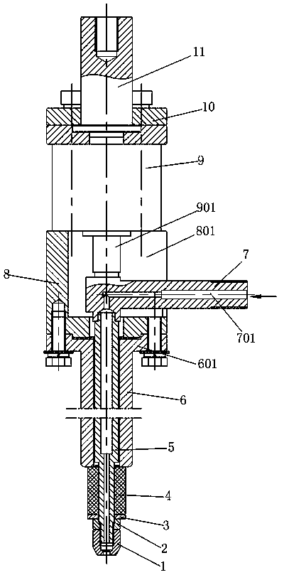
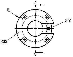
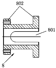
[0015] Such as Figure 1~3 As shown, the present invention includes a hollow tubular central rod 5, the central rod 5 is slidably sleeved in the sleeve 6, the central rod 5 can move up and down in the sleeve 6, the lower end of the central rod 5 is fixedly equipped with a nut 2, an elastic sealing ring 4 And the gasket 3 is set on the center rod 5 between the casing 6 and the nut 2. The elastic sealing ring 4 can be a rubber sealing ring or a silicone sealing ring. A ball nut 1 is provided under the nut 2. The ball nut 1 is used In anti-loosening. The upper end of the casing 6 is provided with a flange 601, and the upper end of the casing 6 is fixedly connected to the lower end of the connecting body 8 by bolts through the flange 601. Connect the upper end of the cylinder body of cylinder 9, connecting rod 11 can conne...


PUM


Abstract

The invention relates to a special pressure head for the hydrostatic testing of a gas cylinder. The special pressure head is characterized by comprising a hollow pipe-shaped central rod sleeving in a sleeve in a sliding manner, wherein a nut is fixedly mounted at the lower end of the central rod, and the central rod between the sleeve and the nut is sleeved with an elastic seal ring and a gasket; the upper end of the sleeve is connected to the lower end of a connecting body, the lower end of a cylinder body of a gas cylinder is fixedly connected to the upper end of the connecting body, and a connecting rod is fixedly connected to the upper end of the cylinder body of the gas cylinder; a groove extending to the upper end of the connecting body is formed in one side of a barrel of the connecting body; and one end of a horizontally-arranged high-pressure connecting rod penetrates through the groove of the connecting body and is fixedly connected to the upper end of the central rod, the high-pressure connecting rod is provided with a through hole and is communicated with an inner hole of the central rod, and a piston rod of the gas cylinder is connected with the connecting rod. The special pressure head is simple and compact in structure, convenient and rapid to operate and reliable to seal, the bearing of an axial force of the gas cylinder is avoided, the efficiency of the testing operation is improved, the requirement of automatic operation is met, the labor intensity of workers is relieved, and the applicability is improved.

Description

technical field [0001] The invention relates to a gas cylinder pressurization test device, in particular to a special indenter for the gas cylinder hydrostatic test. Background technique [0002] At present, when carrying out hydraulic pressurization tests on pressure gas cylinders, it is usually necessary to manually tighten the pressure head with external threads into the internal threads at the inlet and outlet of pressure gas cylinders, and use the surface of the external thread of the pressure head to Wrap raw material tape or apply sealant to seal, or use sealing gasket to seal; Publication No. 101457859A (named "Internal Pressure Sealed Threaded Joint") and Publication No. 202972314U (named "Special Compression Joint for Pressure Vessel Hydrostatic Test") ) for the hydraulic test pressure head disclosed in the patent literature, the pressure head is threadedly connected to the inlet and outlet of the pressure gas cylinder and the elastic sealing gasket is expanded and...

Claims


Application Information

Patent Timeline
Patent Type & Authority Patents(China)
IPC IPC(8): G01N3/12
CPCG01N3/12
Inventor 堵晓春丁正心鄢文国
Owner 无锡昌华机电制造有限公司
Learn More