
Oil sample pretreatment device used in oil pollution prevention and control of aviation equipment and using method thereof

A pretreatment device and oil pollution technology, applied in the preparation of test samples, etc., can solve the problems of affecting the accuracy of monitoring results, long oil sample pretreatment time, and affecting monitoring efficiency, so as to shorten the pretreatment time, Avoid uneven dispersion again and improve the effect of automation

Inactive Publication Date: 2016-11-09
PLA NO 5719 FACTORY
View PDF6 Cites 5 Cited by
  • Summary
  • Abstract
  • Description
  • Claims
  • Application Information

AI Technical Summary

Problems solved by technology

However, the existing technology has the following shortcomings in solving the oil sample pretreatment. First, the oil cleanliness monitoring test time is only 2 to 3 minutes, and the oil sample pretreatment time includes hand shaking for 5 minutes and ultrasonic defoaming treatment for 1 minute. Requires 6 minutes, longer preprocessing time, twice the monitoring time
In the case of a large amount of monitoring tasks, the problem of long oil sample pretreatment time becomes more and more prominent
The second is that the monitoring operator cannot perform other monitoring operations when the hand-cranked sampling bottle is mixing the oil sample, which affects the monitoring efficiency
The third is to carry out ultrasonic defoaming treatment after mixing the oil sample by hand. During the defoaming process, the solid particles in the oil sample will still settle down due to gravity, resulting in uneven distribution and affecting the monitoring results. accuracy

Method used


Image

  • Oil sample pretreatment device used in oil pollution prevention and control of aviation equipment and using method thereof

Examples


Embodiment Construction

[0021] The present invention will be further described below in conjunction with the accompanying drawings, but the protection scope of the present invention is not limited to the following description.

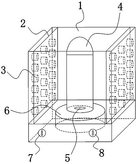
[0022] Such as figure 1 As shown, an oil sample pretreatment device for oil pollution prevention and control of aviation equipment includes a cleaning chamber 1, a transducer vibrator 3, a sampling bottle 4 and a magnetic stirring active device 6. The cleaning chamber 1 is a hollow cuboid structure, An ultrasonic vibrating plate 2 is respectively fixed on a pair of opposite side walls of the cleaning cavity 1, and a plurality of transducer vibrators 3 are fixed on the ultrasonic vibrating plate 2, and the transducer vibrators 3 are connected to the ultrasonic generator, and the magnetic force The stirring active device 6 is fixed on the bottom of the cleaning cavity 1, the driven stirrer 5 is arranged in the sampling bottle 4, and the magnetic stirring active device 6 is driv...


PUM


Abstract

The invention relates to an oil sample pretreatment device used in oil pollution prevention and control of aviation equipment and belongs to the technical field of oil sample pretreatment devices. The oil sample pretreatment device comprises a cleaning cavity, transducer oscillators, a sampling bottle and a magnetic stirring driving device, wherein the cleaning cavity is of a hollow cuboid structure, ultrasonic vibration plates are respectively fixed to two opposite side walls of the cleaning cavity, multiple transducer oscillators are fixed to the ultrasonic vibration plates and are connected with an ultrasonic generator, the magnetic stirring driving device is fixed to the bottom of the cleaning cavity, a driven stirrer is arranged in the sampling bottle, the magnetic stirring driving device is in driving connection with the driven stirrer, the sampling bottle is fixed to the magnetic stirring driving device during processing, and a liquid medium matched with ultrasonic defoaming treatment is contained in the cleaning cavity. The invention further discloses a usage method of the oil sample pretreatment device. The oil sample pretreatment device has the advantages that ultrasonic defoaming treatment can be performed while solid particulate matter of an oil sample are evenly mixed, the treatment efficiency is high, a treatment effect is good, and the automation degree is high.

Description

technical field [0001] The invention relates to the technical field of oil sample pretreatment devices, in particular to an oil sample pretreatment device for prevention and control of oil pollution in aviation equipment and a method for using the same. Background technique [0002] The reliability of the aircraft hydraulic system is extremely high. When performing flight missions, once the hydraulic system fails to operate, there is a danger of aircraft destruction and human death. The pollutants in the aviation hydraulic oil system are the main factors that cause the failure of the hydraulic system. The pollutants in the aviation hydraulic oil system mainly include solid particles, water, air, chemicals and microorganisms, and solid particles are the most common , the most harmful effect. It will accelerate the wear of hydraulic components, shorten the life, reduce the performance, and even cause the valve core to be stuck and the oil filter to be blocked. Therefore, it i...

Claims


Application Information

Patent Timeline
Patent Type & Authority Applications(China)
IPC IPC(8): G01N1/28G01N1/38
CPCG01N1/28G01N1/38
Inventor 凌曦彭敏志张翔宇罗明林寇德均钟友鹏
Owner PLA NO 5719 FACTORY
Learn More