
Movable extending-and-contracting control method for electrical equipment support in underground comprehensive pipe gallery

A technology of electrical equipment and control methods, applied in the direction of mechanical equipment, supporting machines, etc., to achieve the effects of stable connection, simple structure, and convenient installation

Pending Publication Date: 2016-11-09
SHANGHAI MUNICIPAL ENG DESIGN INST GRP
View PDF9 Cites 3 Cited by
  • Summary
  • Abstract
  • Description
  • Claims
  • Application Information

AI Technical Summary

Problems solved by technology

In addition, in some special application places, adjusting the installation height of the equipment still cannot meet the needs of the site, and the electrical equipment needs to be moved on the plane, and the orientation of the equipment operation surface needs to be changed

Method used


Image

  • Movable extending-and-contracting control method for electrical equipment support in underground comprehensive pipe gallery
  • Movable extending-and-contracting control method for electrical equipment support in underground comprehensive pipe gallery
  • Movable extending-and-contracting control method for electrical equipment support in underground comprehensive pipe gallery

Examples


Embodiment Construction

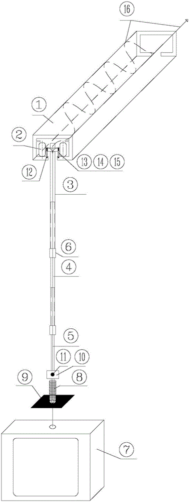
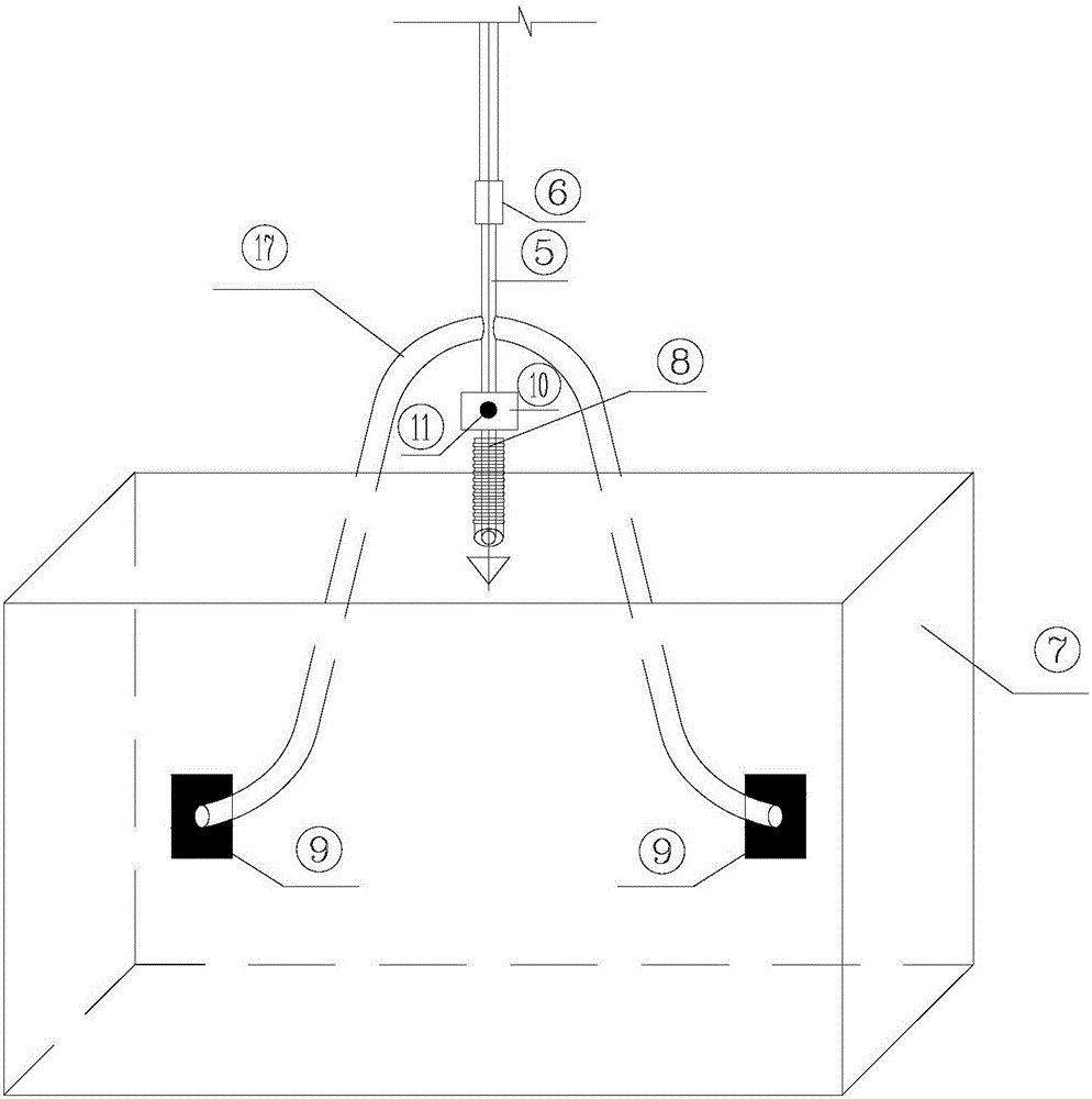
[0042] like figure 1 As shown, the present invention implements a movable and telescopic control method for electrical equipment in an underground comprehensive utility gallery through a movable and telescopic electrical equipment bracket, the electrical equipment bracket including a translation mechanism, a telescopic mechanism, a connection mechanism, and a control unit. Among them, the translation mechanism includes slide rail 1, walking wheel 2, electromagnet 13, spring 14, limit pin 15, etc.; 5 (telescopic rod); the connection mechanism includes a locking sleeve 6, a fixed pin and a hasp; the control unit includes a control box 10, a control button 11, and a cable 16. The bottom of the electrical equipment support is additionally provided with a flexible pipe 8 and a welding plate 9 for connecting the electrical equipment 7 .

[0043] like image 3As shown, the slide rail 1 of the translation mechanism is generally a rectangular frame with a through groove at the bottom...


PUM


Abstract

The invention relates to a movable extending-and-contracting control method for an electrical equipment support in an underground comprehensive pipe gallery. The electrical equipment support is arranged in the underground comprehensive pipe gallery so that a fixing rod can move in a horizontal sliding rail along with walking wheels or can be located and stops moving; and the height of the equipment is adjusted by adjusting the distance between the portion, inserted into a front rod, of any level of extending-and-contracting rod behind the fixing rod and the front rod; a sector-shaped fixing pin is inserted into a sector-shaped pin hole aligned with the sector-shaped fixing pin in the radial direction to connect every two adjacent rods, and loosening and falling of the sector-shaped fixing pins are limited doubly through hasps and locking sleeves; and within the extending-and-contracting length range of locking sleeve extending-and-contracting joints, covering of the sector-shaped pin holes in the all the levels of connected rods, exposure of the fixing pins and hiding of two stations can be achieved. According to the movable extending-and-contracting control method, all the levels of rods serve as cable penetrating pipes for input and output of cables of the electrical equipment, a cable winding frame is arranged on the sliding rail, and the cable supporting function and the cable winding, unwinding, extending and contracting functions are achieved. According to the movable extending-and-contracting control method, the height and plane position can be adjusted through longitudinal extending and contracting and translation, and the method is especially suitable for electrical equipment mounting under the condition that the space is narrow or the operation position needs to be changed frequently.

Description

technical field [0001] The invention relates to an electrical equipment support, in particular to a movable telescopic control method for the electrical equipment support in an underground comprehensive utility gallery. Background technique [0002] In engineering applications, electrical equipment often adopts a fixed installation method, which is installed on various types of steel or fixed on walls and cylinders. Considering the convenience of personnel operation, the installation height of electrical equipment is often between 1.2 and 1.5m. However, in places such as various tunnels with narrow spaces, or because of the narrow passage itself or the centralized installation of electrical equipment, it is sometimes difficult to meet the space or personnel operation requirements for fixed installation of electrical equipment. For example, when the installation location of electrical equipment needs to occupy the passage of personnel or equipment, the installation height of ...

Claims


Application Information

Patent Timeline
Patent Type & Authority Applications(China)
IPC IPC(8): F16M13/02
CPCF16M13/02
Inventor 李双凤
Owner SHANGHAI MUNICIPAL ENG DESIGN INST GRP
Learn More