
Compressor

A compressor and compression mechanism technology, applied in the field of compressors, can solve problems such as the adverse effects of heat exchangers and the performance of air-conditioning systems, and achieve the effects of small oil discharge, high energy efficiency, and reduced oil discharge

Active Publication Date: 2016-11-09
GUANGDONG MEIZHI COMPRESSOR
View PDF10 Cites 4 Cited by
  • Summary
  • Abstract
  • Description
  • Claims
  • Application Information

AI Technical Summary

Problems solved by technology

[0002] In the related art, during the operation of the hermetic rotary compressor, a large amount of lubricating oil is carried by the refrigerant airflow into the upper space of the motor, where separation occurs in the upper space of the motor, and the separated lubricating oil gathers on the upper part of the motor and flows along the housing and The gap between the motors flows back downwards. When the backflow speed is not enough, oil accumulation will be formed on the upper part of the motor; the tiny oil droplets that have not been separated will be discharged from the compressor with the refrigerant airflow, forming an oil discharge volume and forming on the surface of the heat exchanger. The oil film will have adverse effects on the heat exchanger of the air conditioner and affect the performance of the air conditioner system

Method used


Image

  • Compressor
  • Compressor
  • Compressor

Examples


Embodiment 1

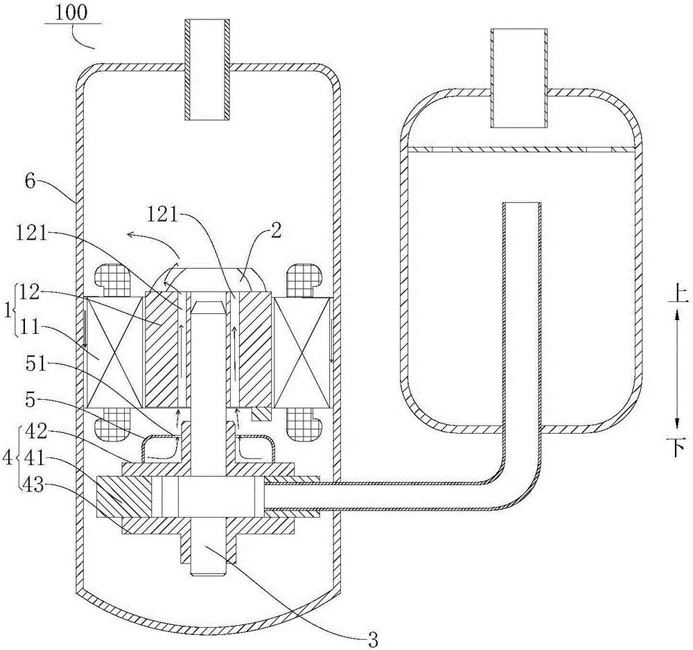
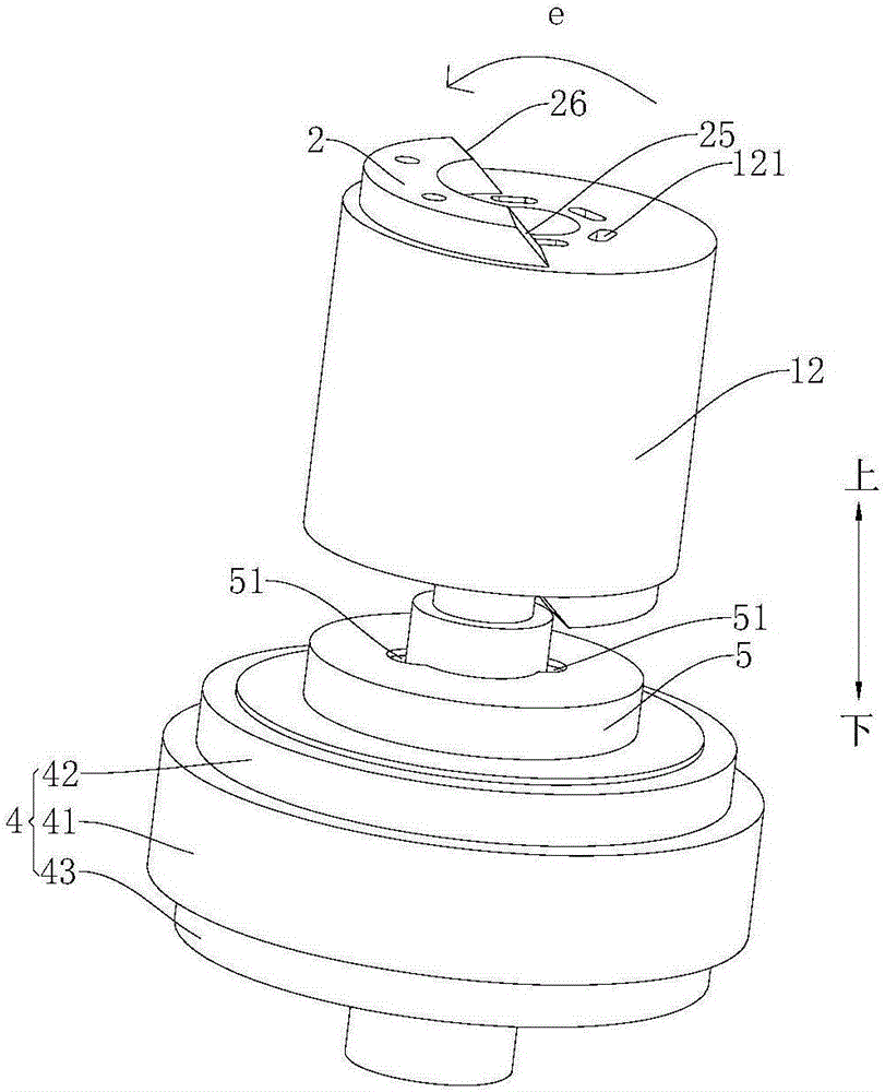
[0074] Such as Figure 1-Figure 7 , Figure 10 and Figure 11 As shown, the compressor 100 according to the embodiment of the present invention includes a motor 1 , a crankshaft 3 , a compression mechanism 4 , a muffler cover 5 and a casing 6 .

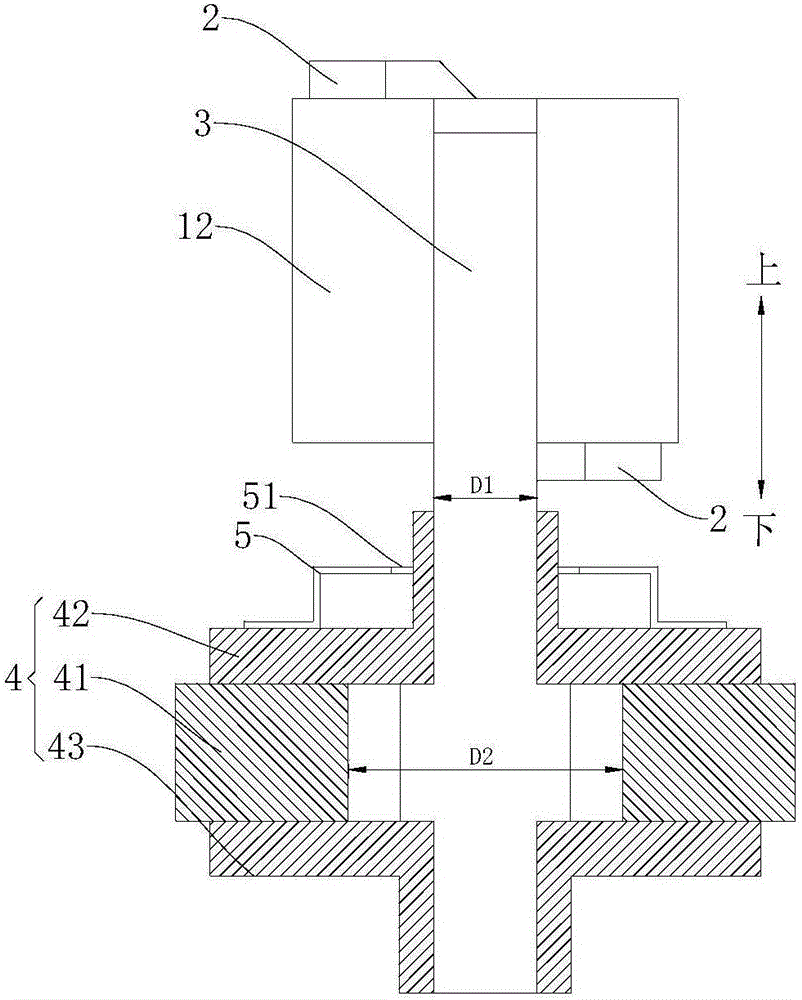
[0075] Specifically, such as figure 1 As shown, the motor 1 includes a stator 11 and a rotor 12 , the stator 11 is sheathed on the rotor 12 , the rotor 12 is provided with an exhaust channel 121 penetrating up and down, and the upper end surface of the rotor 12 is provided with a balance weight 2 . The upper end of the crankshaft 3 is connected to the rotor 12 , and the exhaust passage 121 is arranged close to the crankshaft 3 . The muffler cover 5 covers the upper end face of the compression mechanism 4, and the crankshaft 3 passes through the muffler cover 5 and is connected with the compression mechanism 4, wherein the compression mechanism 4 includes an upper bearing 42, a lower bearing 43 and a cylinder 41, and the cylinder 41...

Embodiment 2

[0080] Such as Figure 1-Figure 4 , Figure 8 , Figure 10 and Figure 11 As shown, the structure of this embodiment is substantially the same as that of Embodiment 1, wherein the same components use the same reference numerals, the only difference is that in this embodiment, the sound absorbing cover 5 is provided with a vent hole 51, and the crankshaft 3 Through the air hole 51, the diameter of the crankshaft 3 is D1, and the diameter of the air hole 51 is D4, and D1 and D4 satisfy D4>D1. This can ensure that the refrigerant airflow discharged from the muffler cover 5 is discharged into the exhaust passage 121 through the gap between the vent hole 51 and the crankshaft 3, and flows upward to the space above the rotor 12, effectively reducing the space between the stator 11 and the crankshaft 3. The amount of refrigerant flowing upward through the gap between the housings 6 enables the lubricating oil to flow back to the lower space of the motor 1 through the gap between t...

Embodiment 3

[0082] Such as Figure 1-Figure 4 , Figure 9-Figure 11 As shown, the structure of this embodiment is substantially the same as that of the second embodiment, wherein the same components use the same reference numerals, the only difference is that in this embodiment, a guide ring 52 is provided at the vent hole 51, The guide ring 52 is located above the muffler cover 5 and extends along the circumferential direction of the vent hole 51 . The deflector ring 52 can play a certain guiding role, and can make the refrigerant flow flowing out from the gap between the inner peripheral wall of the vent hole 51 and the outer peripheral wall of the crankshaft 3 smoothly flow into the exhaust passage 121 on the rotor 12, and Flowing to the upper space of the motor 1 effectively reduces the amount of refrigerant flowing upward in the gap between the stator 11 and the housing 6, so that the lubricating oil can smoothly flow back to the lower space of the motor 1 through the gap between th...


PUM


Abstract

The invention discloses a compressor. The compressor comprises a motor, a crankshaft, a compressing mechanism and a noise reduction cover, wherein the motor comprises a stator and a rotor, the stator is arranged on the rotor in a sleeving manner, an exhaust channel is arranged on the rotor, a balancing block is arranged on the upper end surface of the rotor and provided with a first end surface and a second end surface which are oppositely arranged, the first end surface is suitable for being connected with the rotor, the two ends in the extending direction of the balancing block are a windward end part and a leeward end part respectively, the windward end part is connected between the first end surface and the second end surface, and in the direction from the first end surface to the second end surface, the windward end part is inclined toward the leeward end part; the upper end of the crankshaft is connected with the rotor, and the exhaust channel is close to the crankshaft; the compressing mechanism is connected with the lower end of the crankshaft; and the crankshaft penetrates the noise reduction cover which is arranged on the upper end surface of the compressing mechanism in a covering manner, and a vent hole is formed in the noise reduction cover and is opposite to the exhaust channel. According to the compressor provided by the invention, the problem of oil accumulation and discharge is solved.

Description

technical field [0001] The invention relates to the technical field of refrigeration equipment, in particular to a compressor. Background technique [0002] In the related art, during the operation of the hermetic rotary compressor, a large amount of lubricating oil is carried by the refrigerant airflow into the upper space of the motor, where separation occurs in the upper space of the motor, and the separated lubricating oil gathers on the upper part of the motor and flows along the housing and The gap between the motors flows back downwards. When the backflow speed is not enough, oil accumulation will be formed on the upper part of the motor; the tiny oil droplets that have not been separated will be discharged from the compressor with the refrigerant airflow, forming an oil discharge volume and forming on the surface of the heat exchanger. The oil film will adversely affect the heat exchanger of the air conditioner and affect the performance of the air conditioner system...

Claims


Application Information

Patent Timeline
Patent Type & Authority Applications(China)
IPC IPC(8): F04C29/06F04C29/12
CPCF04C29/065F04C29/12
Inventor 曹红军周亚运朱斌生
Owner GUANGDONG MEIZHI COMPRESSOR
Learn More