
A beater capable of repeatedly changing the pulp flow direction

A technology of flow direction and beater, which is applied in the field of industrial pulping and papermaking, can solve problems such as not considering the beating effect, and achieve the effects of improving mechanical processing efficiency, increasing flow volatility, and improving beating efficiency

Active Publication Date: 2018-07-06
江苏可易木业有限公司
View PDF6 Cites 0 Cited by
  • Summary
  • Abstract
  • Description
  • Claims
  • Application Information

AI Technical Summary

Problems solved by technology

This patent reduces the start-up cost by improving the start-up method of the beater shaft, but does not take into account the beating effect

Method used


Image

  • A beater capable of repeatedly changing the pulp flow direction
  • A beater capable of repeatedly changing the pulp flow direction

Examples


Embodiment Construction

[0025] The present invention will be further explained below in conjunction with the accompanying drawings and specific embodiments. It should be understood that the following specific embodiments are only used to illustrate the present invention but not to limit the scope of the present invention. It should be noted that these drawings are all simplified schematic diagrams, and only schematically illustrate the basic structure of the present invention, so they only show the configurations related to the present invention.

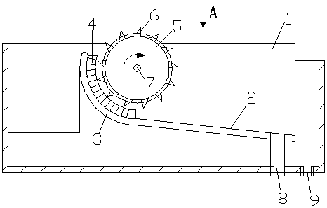
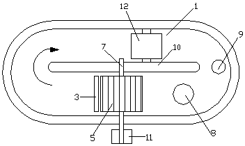
[0026] figure 1 It is a schematic diagram of the structure of the present invention. The arrow in the figure indicates the pulp flow direction. It can be seen from the accompanying drawings that the beater which can repeatedly change the pulp flow direction includes a pulp tank 1, and a flying knife roller 5 is arranged in the pulp tank 1. The bottom of the slurry pool 1 is provided with a sewage outlet 9 and a discharge port 8, the center of the flying k...


PUM


Abstract

The invention provides a beating machine capable of repeatedly changing flow directions of paper pulp. The beating machine comprises a pulp pond. A partition, a washing drum and a flying bar are arranged in the pulp pond, and a drain outlet and a discharge opening are formed in the bottom of the pulp pond. A slope comprises an ascending section and an arc section, the gradient of the ascending section is increased from the bottom of the pulp pond to the vertical lower portion of the flying bar, the arc section is bent from the vertical lower portion of the flying bar to an arc on one side of the downstream portion of the flying bar, and the radian of the arc section is consistent with the circular radian of the flying bar; multiple bottom knives are installed on the arc section and are in a wave shape or a sawtooth shape in the axial direction of the flying bar. When the paper pulp passes through the position between the flying bar and the arc section, the paper pulp flocculates back and forth in the axial direction of the flying bar under the effect of the wave-shaped or sawtooth-shaped bottom knives, the frequency of carrying out mechanical beating treatment on the paper pulp through the bottom knives and flying knives is increased, the time for carrying out mechanical beating treatment on the paper pulp through the bottom knives and the flying knives is prolonged, and the beating efficiency of the paper pulp is improved.

Description

technical field [0001] The invention relates to a beater capable of repeatedly changing the pulp flow direction, belonging to the technical field of industrial pulping and papermaking. Background technique [0002] In the field of papermaking and pulping, it is necessary to beat, crush and stir the pulp raw materials. In the process of beating and crushing, technicians in this industry will use equipment such as beaters. Since the invention of the beater, it has undergone continuous It has been used until now. Although the beater has the disadvantages of large power consumption, large floor space, and intermittent operation, it can handle various pulps of different properties and can be different through changes in operating conditions. The required pulp characteristics have a wide range of adaptation and great flexibility. Therefore, the beater will still be used in domestic paper mills. It is especially suitable for special process production lines for processing cotton,...

Claims


Application Information

Patent Timeline
Patent Type & Authority Patents(China)
IPC IPC(8): D21D1/04D21D1/02
CPCD21D1/02D21D1/04
Inventor 钱国东
Owner 江苏可易木业有限公司
Learn More