A detonator lock device
A detonator and locking technology, which is applied in the field of locking devices, can solve the problems of low operating safety factor, poor sealing performance of fire detonators, and high processing difficulty, and achieves the effects of high safety factor, good sealing performance and convenient operation.
- Summary
- Abstract
- Description
- Claims
- Application Information
AI Technical Summary
Problems solved by technology
Method used
Image

Examples
Embodiment 1
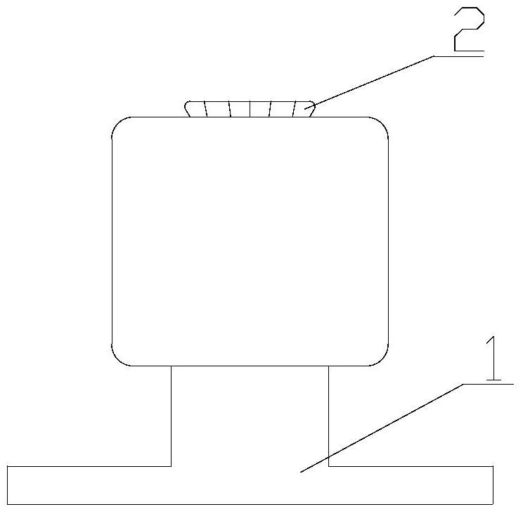
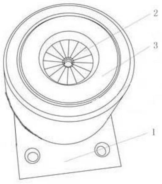
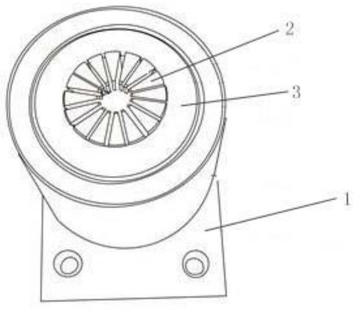
[0045] pass Figure 1-Figure 5 Further illustrate the structure and working principle of the detonator locking device of the present invention, by Figure 1-Figure 3 It can be seen that the detonator lock device of the present invention includes a base 1 , a lock body 2 fixed on the base 1 , and a lock sleeve 3 .
[0046] Figure 4 Shown is figure 1 Schematic diagram of the lock body in . Depend on Figure 4It can be seen that the locking body 2 includes a bottom connecting tube 21 and a locking tube 22 extending on the bottom connecting tube 21 , and the locking body 2 is fixed on the base 1 through the bottom connecting tube 21 . The outer surface of the locking tube 22 is an outer tapered surface with a large upper part and a smaller lower part, and the locking tube 22 is evenly divided into a plurality of radially extending bayonets 23 along its circumferential direction.
[0047] Figure 5 Shown is figure 1 Schematic diagram of the structure of the lock sleeve. De...
Embodiment 2
[0052] The difference between this embodiment and embodiment 1 is: as Figure 6 and Figure 7 As shown, the detonator lock device also includes an adjustment rod 4, and one end of the adjustment rod 4 is from Figure 4 The shown bottom connecting pipe 21 extends into the lock tube 22, and is used to adjust the axial position of the fire detonator to be clamped in the lock tube 22, so as to be suitable for processing different numbers of fire detonators.
[0053] Further preferably, the base 1 is provided with an axial cavity, and the bottom connecting pipe 21 of the locking body 2 is inserted into the axial cavity of the base 1, and the bottom end of the axial cavity is provided with an inner socket for blocking the bottom connecting pipe 21. The overturn edge 10 and the bottom connecting pipe 21 are detachably fixed on the base 1 through a limiting mechanism, and the limiting mechanism includes a hollow bolt 5 . Such as Figure 8 The structure of the hollow bolt 5 is shown...
Embodiment 3
[0059] The difference between this embodiment and embodiment 2 is: as Figure 10 As shown in the structural diagram of the lock body, the flap of the lock tube 22 is provided with two protrusions 23 from top to bottom. When the lock tube 22 is locked, the protrusions 23 respectively fit together to form a ring structure. In the process of locking the lock tube 22, two sealing rings are produced between the fire detonator and the fuse, which further improves the sealing between the fire detonator and the fuse.
PUM
| Property | Measurement | Unit |
|---|---|---|
| height | aaaaa | aaaaa |
Abstract
Description
Claims
Application Information
 - R&D
- Intellectual Property
- Life Sciences
- Materials
- Tech Scout
- Unparalleled Data Quality
- Higher Quality Content
- 60% Fewer Hallucinations
Browse by: Latest US Patents, China's latest patents, Technical Efficacy Thesaurus, Application Domain, Technology Topic, Popular Technical Reports.
© 2025 PatSnap. All rights reserved.Legal|Privacy policy|Modern Slavery Act Transparency Statement|Sitemap|About US| Contact US: help@patsnap.com