
A kind of optical glue bonding equipment

A bonding equipment and optical glue technology, applied in chemical instruments and methods, layered products, lamination devices, etc., can solve problems such as air bubbles, high production costs, and insufficient adhesion, and achieve simple equipment structure and low equipment cost , to improve the effect of transparency

Active Publication Date: 2018-06-01
SHENZHEN CHENG XI ELECTROMECHANICAL EQUIP +1
View PDF4 Cites 0 Cited by
  • Summary
  • Abstract
  • Description
  • Claims
  • Application Information

AI Technical Summary

Problems solved by technology

[0003] However, traditional OCA and LOCA materials have disadvantages: ① strict requirements on process technology and equipment, and high production costs; ② large-scale lamination is difficult; ③ it is difficult to solve the problem of air bubbles in full lamination, and the production yield is low; ④ It is very difficult to rework if there is a quality problem in the bonding process, resulting in the scrapping of the expensive touch screen body and increasing production costs
[0005] Compared with traditional OCA and LOCA laminating equipment, the development of OHA optical adhesive laminating equipment is relatively late, and the laminating equipment in the prior art cannot adapt to the OHA process technology. The existing laminating machine laminating technology can only complete lamination. The protective film cannot meet the bonding requirements of OHA. After bonding, the adhesion is not enough, and it is easy to produce bubbles, wrinkles, indentations, crushing and water ripples, etc.

Method used


Image

  • A kind of optical glue bonding equipment
  • A kind of optical glue bonding equipment

Examples


Embodiment Construction

[0022] In order to facilitate the understanding of the present invention, the present invention will be described more fully below with reference to the associated drawings. Preferred embodiments of the invention are shown in the accompanying drawings. However, the present invention can be embodied in many different forms and is not limited to the embodiments described herein. On the contrary, the purpose of providing these embodiments is to make the disclosure of the present invention more thorough and comprehensive.

[0023] It should be noted that when an element is referred to as being “fixed” to another element, it can be directly on the other element or there can also be an intervening element. When an element is referred to as being "connected to" another element, it can be directly connected to the other element or intervening elements may also be present. The terms "vertical," "horizontal," "left," "right," and similar expressions are used herein for purposes of ill...


PUM

PropertyMeasurementUnit
transmittivityaaaaaaaaaa

Abstract

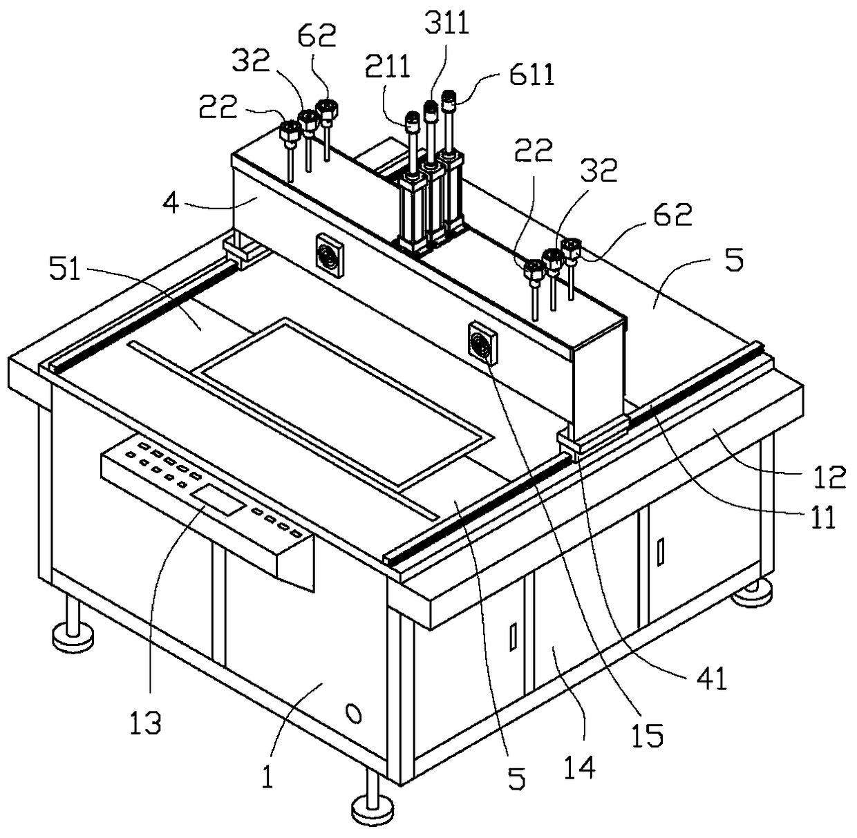
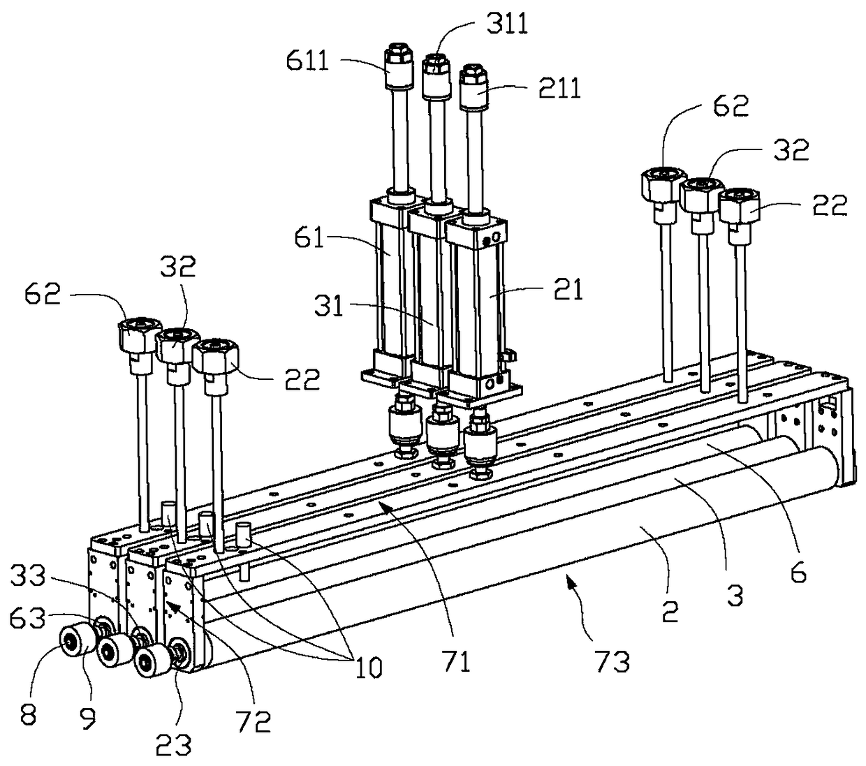
Provided is optical adhesive laminating equipment. The optical adhesive laminating equipment comprises a rack, a laminating mechanism arranged on the rack, an operation platform and a controller; the laminating mechanism comprises a bubble removing roller, a first cylinder connected with the bubble removing roller, a primary high-temperature roller and a second cylinder connected with the primary high-temperature roller and a portal frame which is arranged on the rack and can shift in a reciprocating mode along the rack, and the bubble removing roller, the first cylinder, the primary high-temperature roller and a second cylinder are arranged on the portal frame respectively; the operation platform comprises a bottom die, vacuum adsorption holes formed in the bottom die and a vacuum adsorption device connected with the vacuum adsorption holes, and the controller is in signal connection with the laminating mechanism and the operation platform. Compared with existing laminating equipment, according to the hot-pressing laminating equipment, air in a material is removed through the bubble removing roller before laminating is conducted, and bubbles are avoided; the high-temperature rollers synchronously press downwards, laminating adhesion is adjusted, and corrugations, indentations, crushed damage, water corrugations and the like generated after laminating are eliminated.

Description

technical field [0001] The invention relates to an optical adhesive bonding equipment. Background technique [0002] The adhesive materials of traditional touch screens are OCA (Optically Clear Adhesive) and LOCA (Liquid Optical Clear Adhesive). OCA is to make optical acrylic adhesive without substrate, and then attach a layer of release film to the upper and lower bottom layers. , is a double-sided laminating tape without matrix material, and is the best adhesive for touch screens. LOCA is colorless and transparent, with a light transmittance of more than 98%, good bonding strength, and can be cured at room temperature or medium temperature. It also has the characteristics of small curing shrinkage and yellowing resistance. Compared with OCA, LOCA is used in some application fields It has particular advantages and can solve the limitations faced by OCA tapes. [0003] However, traditional OCA and LOCA materials have disadvantages: ① strict requirements on process technolo...

Claims


Application Information

Patent Timeline
Patent Type & Authority Patents(China)
IPC IPC(8): B32B37/00B32B37/06B32B37/10
CPCB32B37/003B32B37/06B32B37/10
Inventor 张永洁陈云钢
Owner SHENZHEN CHENG XI ELECTROMECHANICAL EQUIP
Learn More