Floor mopping machine and spraying structure of same

A mopping machine and nozzle technology, applied in the field of mopping machines, can solve the problems of compression volume, inconvenient use, large bottom shell volume, etc., and achieve the effects of weight reduction, ease of use, and convenient use

Inactive Publication Date: 2016-11-09
俞少蔚
View PDF5 Cites 0 Cited by
  • Summary
  • Abstract
  • Description
  • Claims
  • Application Information

AI Technical Summary

Problems solved by technology

[0006] Aiming at the disadvantages of the prior art that the floor mopping machine equipped with a water spray device has a large volume and is inconvenient to use, the present invention provides a spray structure of the floor mopping machine. By redesigning the spray structure, not only can compress The volume of the bottom shell is reduced, and the spray structure is effectively simplified, so that backflow and dripping can be prevented without a one-way valve

Method used


Image

  • Floor mopping machine and spraying structure of same
  • Floor mopping machine and spraying structure of same
  • Floor mopping machine and spraying structure of same

Examples


Embodiment 1

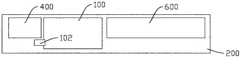
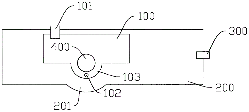
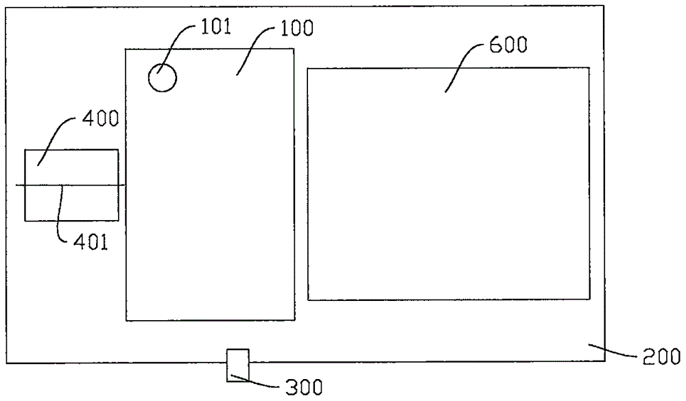
[0030] Such as Figure 1-3 As shown, the legend shown in the drawings is a brief explanatory diagram, and for the sake of clarity, the proportional relationship of the components between the various drawings is not one-to-one correspondence.

[0031] A sprinkler structure for a mopping machine, comprising a tank 100 and a pump device 400 for sucking liquid in the tank 100 and spraying it out through a nozzle 300 provided on a bottom shell 200 of the mopping machine. The box body 100 is used to hold the spraying liquid of the mopping machine. Generally, the liquid that can be used includes water, and in some cases, other liquid sprays can also be used. The pump device 400 can use various types of pumps, including gear pumps or diaphragm pumps, and can also use other similar pumps. The spray structure described in this embodiment makes it possible to use other types of pumps. The pump device 400 sprays the liquid for spraying from the nozzle 300 by suction. The above-mentioned...

Embodiment 2

[0049] A floor mopping machine using the spray structure described in the above-mentioned embodiment 1, including the spray structure described in the above-mentioned embodiment 1, wherein the pump device 400 of the spray structure is controlled by a control device connected in a wireless manner . The control unit can be placed in the handle of the mopping machine, or it can be separated from the mopping machine as an independent part.

[0050] Further, the pump device 400 includes a gear pump or a diaphragm pump, and other similar pumps may also be used.


PUM


Abstract

The invention relates to cleaning equipment suitable for household use, and discloses a spraying structure of a floor mopping machine. The spraying structure comprises a tank and a pump unit, and the pump unit is used for pumping liquid in the tank and spraying out the liquid via a nozzle arranged on a bottom shell on the outer side of the mopping machine. The tank is provided with a liquid inlet and a liquid outlet. The inlet of the pump unit is connected with the liquid outlet. The outlet of the pump unit is connected with the nozzle and the mopping machine. The spraying structure has the advantages that dripping and backflow of the nozzle can be avoided without a one-way valve, and the floor mopping machine is small in integral thickness and suitable for being used in narrow household spaces, thereby having high application value.

Description

technical field [0001] The present invention relates to a cleaning device suitable for home use, in particular to a spray structure of a floor mopping machine and a floor mopping machine made by applying the pengling structure. The spray structure has a newly designed internal structure arrangement, The utility model is suitable for use on the existing floor mopping machine, and can better improve the use experience of the floor mopping machine. Background technique [0002] Mop, also known as floor mop, is a floor cleaning tool that is often used in traditional families. For families who are not used to or do not like equipment such as vacuum cleaners, mops are a more suitable cleaning tool. Traditionally, when using a mop, the user adopts a vertical position and needs to continuously drag the mop back and forth to achieve cleaning. [0003] In the prior art, there have been similar devices driven by electricity, which can be called mopping machines. Existing floor moppi...

Claims


Application Information

Patent Timeline
Patent Type & Authority Applications(China)
IPC IPC(8): A47L11/28A47L11/40
CPCA47L11/28A47L11/408A47L11/4088
Inventor 俞少蔚
Owner 俞少蔚
Why Eureka
Try Eureka