
Motor noise reduction structure

A technology of noise reduction and motor cover, applied in the direction of exhaust diffuser, cleaning equipment, vacuum cleaner, etc., can solve the problems of unsatisfactory sound absorption effect and limited noise reduction space, and achieve the effect of preventing resonance, eliminating noise and eliminating wind noise

Active Publication Date: 2016-11-09
SKYBEST ELECTRIC APPLIANCE SUZHOU CO LTD
View PDF6 Cites 13 Cited by
  • Summary
  • Abstract
  • Description
  • Claims
  • Application Information

AI Technical Summary

Problems solved by technology

But the shortcomings are also very obvious, that is, the sound absorption effect is not ideal, and the noise reduction space is limited

Method used


Image

  • Motor noise reduction structure
  • Motor noise reduction structure
  • Motor noise reduction structure

Examples


no. 1 example

[0035] like

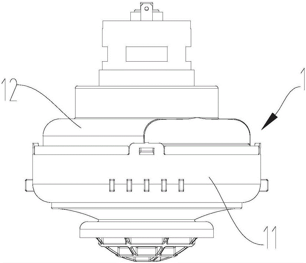
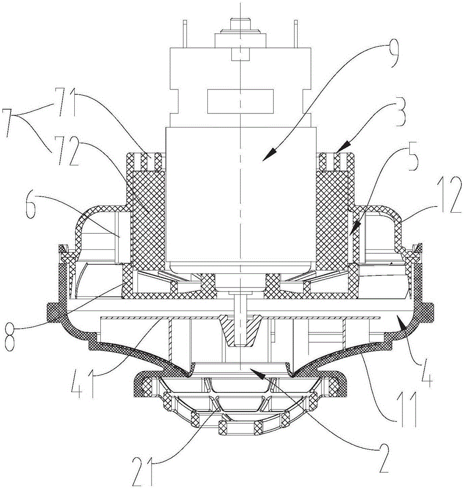
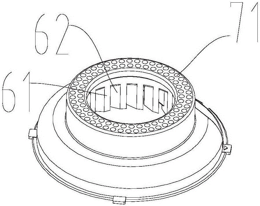
[0036] figure 1 , figure 2 As shown, a motor noise reduction structure includes a motor cover 1 for accommodating a motor 9, and the motor cover 1 includes a moving impeller chamber 4 and a muffler chamber 5 in sequence from the air inlet 2 to the air outlet 3, and the moving impeller chamber 4 is provided with a moving impeller assembly 41, and the sound-absorbing cavity 5 is provided with a first sound-absorbing portion 6 and a second sound-absorbing portion 7, and the first sound-absorbing portion 6 includes an oblique grid, and is arranged on the first sound-absorbing portion The second muffler portion 7 downstream of 6 includes dense small holes 71 arranged at the air outlet 3 and a muffler material 72 arranged inside the air outlet 3 . In this embodiment, the motor cover 1 includes a wind cover 11 and a muffler cover 12 sealingly engaged with the wind cover 11, the moving impeller cavity 4 is arranged in the wind cover 11, the sound-absorbing chamber 5 i...

no. 2 example

[0045] like Figure 8 As shown, the motor noise reduction structure of this embodiment is basically the same as that of the first embodiment, the difference is that only the first noise reduction part 6 is provided in the noise reduction cover 12, that is, only oblique grids are provided.

no. 3 example

[0047] like Figure 9 As shown, the motor noise reduction structure of this embodiment is basically the same as that of the first embodiment, the difference is that only the second noise reduction part 7 is provided in the noise reduction cover 12, that is, only the dense small holes arranged at the air outlet 3 are provided. 71 and the sound-absorbing material 72 arranged inside the air outlet 3 .


PUM

PropertyMeasurementUnit
Apertureaaaaaaaaaa

Abstract

The invention relates to a motor noise reduction structure, in particular to a dust collector motor noise reduction structure. The structure comprises a motor cover for containing a motor. The motor cover internally comprises an impeller cavity and a sound elimination cavity in sequence from an air inlet to an air outlet. A movable impeller assembly is arranged in a movable impeller cavity. A first sound elimination part and / or a second sound elimination part are / is arranged in the sound elimination cavity, the first sound elimination part comprises an oblique grid, and the second sound elimination part comprises small dense holes formed in the air outlet and a sound elimination material arranged on the inner side of the air outlet. The air noise can be effectively reduced.

Description

technical field [0001] The invention relates to a motor noise reduction structure, in particular to a vacuum cleaner motor noise reduction structure. Background technique [0002] The vacuum cleaner uses a motor as a power device to drive the impeller assembly to work. The vacuum cleaner will generate airflow when it is working, and it will generate noise when the airflow passes through the cavity of the motor cover. The magnitude of the noise will vary depending on the structure and material of the cavity of the motor cover. In the case of DC vertical vacuum cleaners, due to the design requirements, the size of the whole machine is small, so the space inside the casing is limited, and it is impossible to install a complicated sound-absorbing structure, so it will generate a lot of noise during work, which makes the user's operation difficult. The experience is poor and the comfort is not high. [0003] For the above-mentioned technical problems, the usual practice in the ...

Claims


Application Information

Patent Timeline
IPC IPC(8): A47L9/00
CPCA47L9/0081
Inventor 刘海平杨菲菲
Owner SKYBEST ELECTRIC APPLIANCE SUZHOU CO LTD
Learn More