Automatic transfer equipment used for yarn roll

A transfer and automatic technology, applied in the direction of conveyors, mechanical conveyors, transportation and packaging, etc., can solve problems such as safety hazards, low production efficiency, yarn cluster damage, etc., achieve high automation, improve work efficiency, reduce The effect of taking up space

Active Publication Date: 2016-11-02
JUSHI GROUP CHENGDU
View PDF8 Cites 5 Cited by
  • Summary
  • Abstract
  • Description
  • Claims
  • Application Information

AI Technical Summary

Problems solved by technology

Due to the large number of products, the labor intensity of employees' handling is high and the production efficiency is low; at the same time, the operation mode of manual handling makes employees easily injured during the handling process
[0003] The existing yarn ball automatic transfer equipment adopts the way of laying rails on the ground to move, and its own movement occupies too much work space, and the activities of the equipment on the rails during the working process affect the normal production operations of employees and there is a certain degree of safety. Hidden dangers, at the same time, its moving and rotating range is limited, resulting in a limited range of use. During the process of picking and placing yarn rolls, due to the structural design of the picking and placing yarn roll device, it is easy to cause certain damage to the picked and placed yarn rolls. , affecting the quality of the yarn cluster

Method used


Image

  • Automatic transfer equipment used for yarn roll
  • Automatic transfer equipment used for yarn roll
  • Automatic transfer equipment used for yarn roll

Examples


Embodiment Construction

[0019] The present invention will be further described below in conjunction with the accompanying drawings, but the protection scope of the present invention is not limited to the following description.

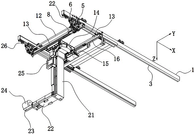
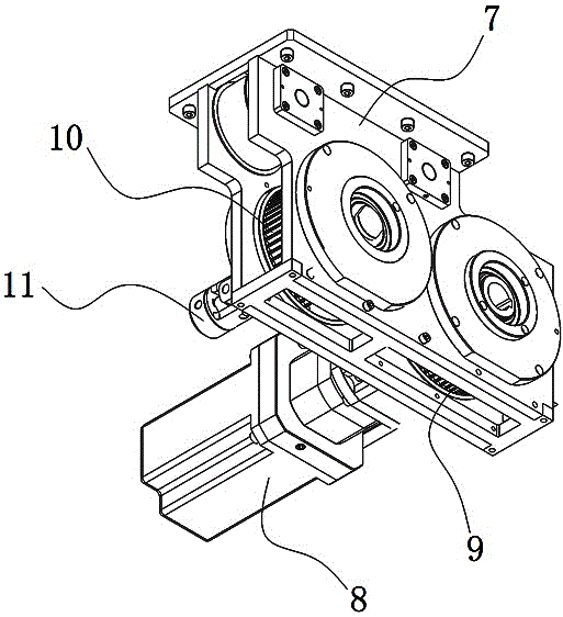
[0020] Such as Figure 1 to Figure 4 As shown, a device for automatic transfer of yarn clusters includes an X-direction moving mechanism, a Y-direction moving mechanism, a rotating mechanism, a lifting mechanism, a telescopic mechanism and a yarn taking plate 23, and the X-direction moving mechanism includes an X-direction track 1 , I-beam 2, pulley 5, X-direction motor 8 and transmission rod 12, two mutually parallel I-beams 2 are installed on the top surface of the workshop, X-direction rail 1 is fixed on the I-beam 2 through hanging parts 4 , a rack 3 is fixed on the lower surface of the X-direction track 1, and a pulley 5 is respectively arranged under the two X-direction rails 1, and each pulley 5 includes a side plate 7, an X-direction motor 8, and an X-direction moving...


PUM


Abstract

The invention relates to automatic transfer equipment used for a yarn roll. The equipment comprises an X-direction moving mechanism, a Y-direction moving mechanism, a rotating mechanism, a lifting mechanism, a telescopic mechanism and a yarn taking plate. The X-direction moving mechanism comprises an X-direction rail, joist steel, a tackle, an X-direction motor and a transmission rod; the Y-direction moving mechanism comprises a Y-direction rail, a Y-direction motion assembly, a Y-direction motor and a synchronous belt; the rotating mechanism comprises a mounting plate, a rotating motor, a rotating driving gear and a rotating driven gear; the upper end of the lifting mechanism is connected with the output end of the rotating driven gear, the telescopic mechanism is connected with the lower end of the lifting mechanism, the yarn taking plate is mounted at the output end of the telescopic mechanism, an industrial camera is arranged at the tail end of the yarn taking plate, infrared sensors used for detecting whether foreign matter exists or not are arranged on the four side walls of the lifting mechanism, and a control panel is arranged on one side of the lifting mechanism; and the automatic transfer equipment has the beneficial effects of being reasonable in structural arrangement, high in taking precision and small in occupied space.

Description

technical field [0001] The invention relates to an automatic transfer device for yarn clusters. Background technique [0002] At present, in the fiber production industry, in the process of fiber production and handling after the fiber is formed into a yarn ball, there are situations where the labor intensity of the employees is high and the working environment is poor. Traditionally, it is necessary to rely on manual work to unload the yarn clusters one by one from the machine and transport them to the delivery trolley. Due to the large number of products, the labor intensity of employees' handling is high and the production efficiency is low. At the same time, the operation mode of manual handling makes employees easily injured during the handling process. [0003] The existing yarn ball automatic transfer equipment adopts the way of laying rails on the ground to move, and its own movement occupies too much work space, and the activities of the equipment on the rails duri...

Claims


Application Information

Patent Timeline
Patent Type & Authority Applications(China)
IPC IPC(8): B65G35/00
CPCB65G35/00
Inventor 吴军陈杰
Owner JUSHI GROUP CHENGDU
Why Eureka
Try Eureka