
High sealing forced air cooling bus duct

A high-sealing, busway technology, used in fully enclosed busbar devices, cooling busbar devices, etc., can solve the problems of single busbar structure, easy condensation of busbars, inability to balance structural strength and heat dissipation, etc., and achieve extended use. Longevity, good sealing performance, and the effect of improving the internal working environment

Inactive Publication Date: 2016-10-26
扬中市美娴电器有限公司
View PDF15 Cites 5 Cited by
  • Summary
  • Abstract
  • Description
  • Claims
  • Application Information

AI Technical Summary

Problems solved by technology

[0002] Busway, especially high-voltage busway and other power supply equipment used in large substations and engineering sites, has gradually replaced the traditional wiring method of bare cables. Using busway wiring is not only safe, beautiful, reliable, but also capable of transmitting large currents. It can effectively eliminate the faults caused by uneven current distribution of double-split and triple-split high-voltage cables, and ensure the reliability of power supply. However, the traditional bus duct structure is relatively single, especially unable to balance the structural strength and heat dissipation requirements, and It is easy to condense in the busway, which will affect the insulation performance of the busway. If we can invent a new type of busway that not only has good sealing performance, but also can perform forced heat dissipation, this kind of problem can be solved. For this reason, we provide a high-tightness Forced cooling busway

Method used


Image

  • High sealing forced air cooling bus duct
  • High sealing forced air cooling bus duct

Examples


Embodiment Construction

[0013] The following will clearly and completely describe the technical solutions in the embodiments of the present invention with reference to the accompanying drawings in the embodiments of the present invention. Obviously, the described embodiments are only some, not all, embodiments of the present invention. Based on the embodiments of the present invention, all other embodiments obtained by persons of ordinary skill in the art without making creative efforts belong to the protection scope of the present invention.

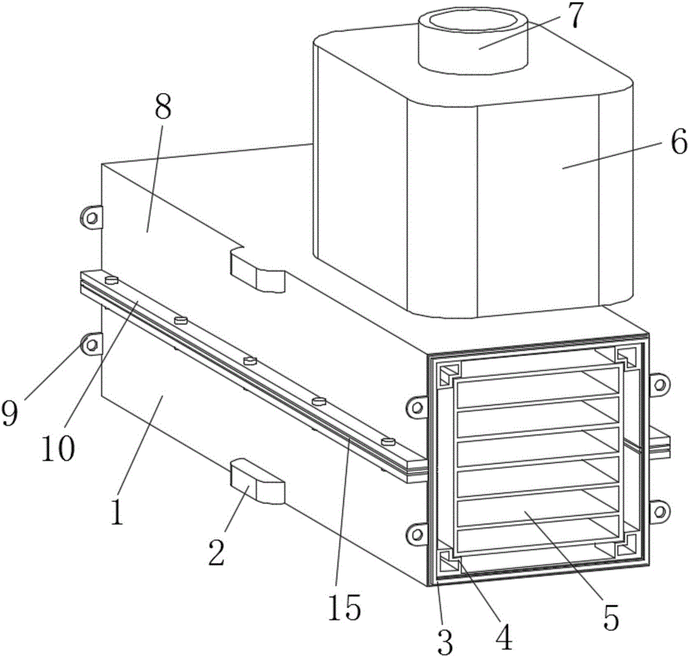
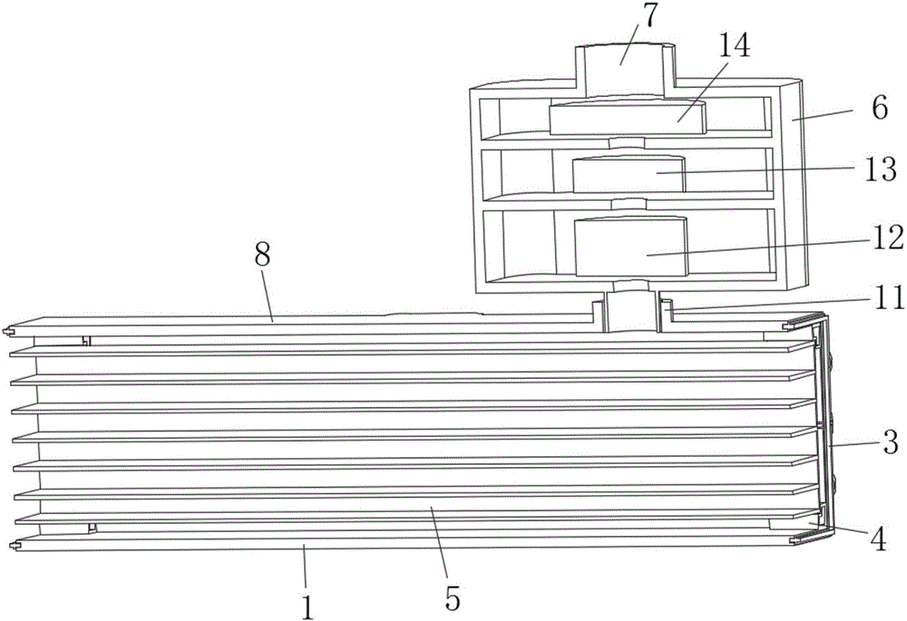
[0014] see Figure 1-2 , the present invention provides a technical solution: a high-tightness forced heat dissipation bus duct, including a lower support plate 1 and an upper support plate 8, and the upper support plate 8 and the lower support plate 1 are screwed and installed through a screw edge 10 , the front and rear ends of the upper support plate 8 and the lower support plate 1 are provided with threaded lugs 9, and the front and rear ends of the upper ...


PUM


Abstract

The present invention discloses a high sealing forced air cooling bus duct. The high sealing forced air cooling bus duct includes a lower support plate and an upper support plate. The upper support plate and the lower support plate are in screw connection with each other through screw-connected edges. Both front ends and rear ends of the upper support plate and the lower support plate are provided with screw-connected lugs. Docking rings are plugged in both the front ends and the rear ends of the upper support plate and the lower support plate. Support protrusions are disposed at bending parts of the lower end of the upper support plate and the upper end of the lower support plate. Internal groove plates are clamped between the support protrusions. The upper end of the upper support plate is provided with a screw connected port. A bus duct structure having good sealing performance and being capable of externally being connected with a heat dissipation device is designed, so that the bus duct has both good structure strength and sealing performance and good heat dissipation performance; and particularly, the heat dissipation device also has dedusting and dehumidifying capabilities, thereby greatly improving an internal working environment of the bus duct so as to prolong the service life of the bus duct.

Description

technical field [0001] The invention relates to the technical field of bus duct design, in particular to a bus duct with high sealing performance and forced heat dissipation. Background technique [0002] Busway, especially high-voltage busway and other power supply equipment used in large substations and engineering sites, has gradually replaced the traditional wiring method of bare cables. Using busway wiring is not only safe, beautiful, reliable, but also capable of transmitting large currents. It can effectively eliminate the faults caused by uneven current distribution of double-split and triple-split high-voltage cables, and ensure the reliability of power supply. However, the traditional bus duct structure is relatively single, especially unable to balance the structural strength and heat dissipation requirements, and It is easy to condense in the busway, which will affect the insulation performance of the busway. If we can invent a new type of busway that not only ha...

Claims


Application Information

Patent Timeline
Patent Type & Authority Applications(China)
IPC IPC(8): H02G5/06H02G5/10
CPCH02G5/06H02G5/10
Inventor 施大春刘坤杨瑞峰
Owner 扬中市美娴电器有限公司
Learn More