System and method for monitoring spatial relative displacement change

A relative displacement and change monitoring technology, applied in the field of electronic information, can solve the problems of inability to quantify distance tracking, accumulation of displacement calculation errors, and high hardware costs

Active Publication Date: 2018-10-26
SHANGHAI OYMOTION INFORMATION TECH
View PDF5 Cites 0 Cited by
  • Summary
  • Abstract
  • Description
  • Claims
  • Application Information

AI Technical Summary

Problems solved by technology

[0003] In recent years, virtual reality and motion sensing technologies have appeared in some game devices; the existing control methods usually use machine vision for posture and displacement detection; such methods are widely used in virtual reality, but there are many shortcomings, such as The machine vision solution using 3D camera and structured light has high hardware cost and high power consumption, and there are requirements for the light of the application, the size of the place, whether there is occlusion, and the detection distance, etc. These requirements limit this technology. the popularity of
Others, such as flying mice and somatosensory guns, can only detect the change of rotation angle by the internal motion sensor without the help of an external camera. Since the error accumulation of displacement calculation cannot be solved, the distance quantitative tracking during displacement movement cannot be done. Class methods cannot solve the problem well for attitude detection with displacement requirements

Method used


Image

  • System and method for monitoring spatial relative displacement change
  • System and method for monitoring spatial relative displacement change
  • System and method for monitoring spatial relative displacement change

Examples


Embodiment 1

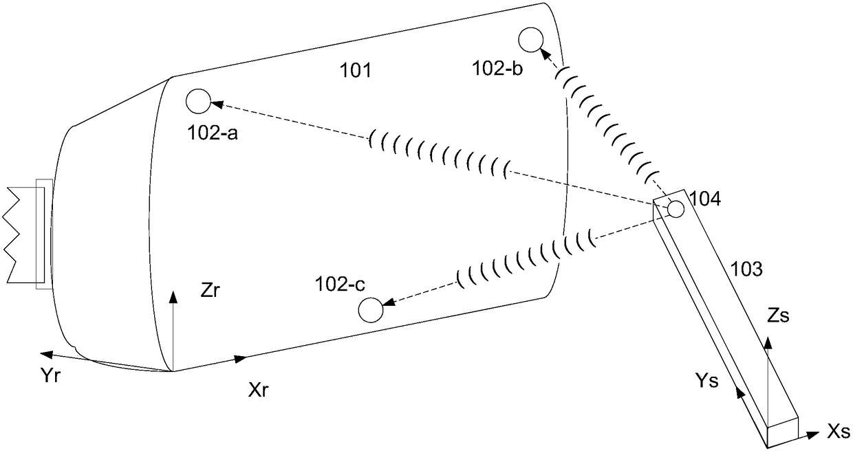
[0072] see figure 1 , the present invention discloses a spatial relative displacement change monitoring system, the monitoring system includes: a first electric pulse mechanism and a first ultrasonic mechanism arranged in the first device 103, a second electric pulse mechanism arranged in the second device 101 . At least three second ultrasonic mechanisms whose centers are not collinear, a timing control module, a distance calculation module, a real-time position determination module, and a rotation angle acquisition module; wherein, the first device or / and the second device are mobile devices. The timing control module is used to control the timing relationship between the electric pulse signal and the ultrasonic signal. The timing control module and the rotation angle acquisition module can be set in the first device, of course, the timing control module and the rotation angle acquisition module can also be set in the second device.

[0073] In this embodiment, the second e...

Embodiment 2

[0113] The difference between this embodiment and Embodiment 1 is that in this embodiment, the first electric pulse mechanism is an electric pulse generator, the second electric pulse mechanism is an electric pulse receiver; the first ultrasonic mechanism is an ultrasonic generator , the second ultrasonic mechanism is an ultrasonic receiver.

Embodiment 3

[0115] The difference between this embodiment and Embodiment 1 is that in this embodiment, the first device can be a TV, and the second device can be a remote control device (the first device does not move, the second device moves; the receiving end does not move, the sending end moves ); the first device can also be a remote control device, and the second device is a TV (the first device moves, the second device does not move; the receiving end moves, and the sending end does not move).


PUM


Abstract

The invention discloses a space relative displacement change monitoring system and method. The monitoring system comprises a first time synchronization mechanism and a first supersonic wave mechanism which are arranged on a first device, a second time synchronization mechanism and at least three supersonic wave mechanisms which are arranged on a second device, a distance calculation module and a real-time position determination module, wherein the at least three supersonic wave mechanisms are not center-colinear; distance calculation module is used for calculating the distance between each second supersonic wave mechanism and the first supersonic wave mechanism, time T obtained by each timer is multiplied by the propagation speed V of supersonic waves, and the distance between a supersonic wave receiver and a supersonic wave generator is obtained; the real-time position determination module comprises a first position determination unit, the first position determination unit is used for determining the position relation between the first device and the second device according to the distances between the second supersonic wave mechanisms and the first supersonic wave mechanism and the positions of the three second supersonic wave mechanisms. According to the invention, the changes of relative movement and displacement of two objects in the space can be precisely obtained.

Description

technical field [0001] The invention belongs to the technical field of electronic information, and relates to a displacement change monitoring system, in particular to a spatial relative displacement change monitoring system. Background technique [0002] With the rapid development of science and technology, the types of electronic products are becoming more and more abundant. Electronic products are usually controlled by a remote controller. [0003] In recent years, virtual reality and motion sensing technologies have appeared in some game devices; the existing control methods usually use machine vision for posture and displacement detection; such methods are widely used in virtual reality, but there are many shortcomings, such as The machine vision solution using 3D camera and structured light has high hardware cost and high power consumption, and there are requirements for the light of the application, the size of the place, whether there is occlusion, and the detection...

Claims


Application Information

Patent Timeline
Patent Type & Authority Patents(China)
IPC IPC(8): G01S11/14
CPCG01S11/14
Inventor 倪华良
Owner SHANGHAI OYMOTION INFORMATION TECH
Why Eureka
Try Eureka