
Automatic tube penetrating packaging machine

A packaging machine and automatic threading technology, which is applied in packaging, transportation and packaging, and individual objects, can solve the problems of lower product packaging yield, acupuncture needle tube wall conflict, and acupuncture needle bending, so as to improve effective work and avoid waste , the effect of improving the yield rate

Active Publication Date: 2016-10-26
江苏凯邦医疗器械有限公司
View PDF7 Cites 5 Cited by
  • Summary
  • Abstract
  • Description
  • Claims
  • Application Information

AI Technical Summary

Problems solved by technology

[0005] But the weak point of above-mentioned this automatic tube-piercing packaging machine is that when the needle pusher works, some deviations will still occur due to the alignment of the acupuncture needles and the plastic tubes. Pushing inside the tube will easily cause the needle head of the acupuncture needle to collide with the wall of the plastic tube, causing the acupuncture needle to bend or even be scrapped, resulting in a large number of defective products during the needle pushing process, thereby reducing the yield rate of product packaging

Method used


Image

  • Automatic tube penetrating packaging machine
  • Automatic tube penetrating packaging machine
  • Automatic tube penetrating packaging machine

Examples


Embodiment 1

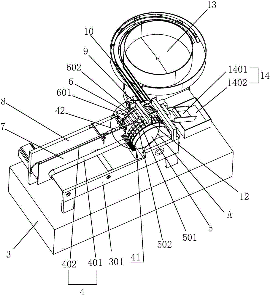
[0039] Embodiment one: an automatic tube-through packaging machine, such as image 3 and Figure 7 As shown, the packaging machine body 3 is included, and the packaging machine body 3 includes a horizontally arranged workbench 301. The workbench 301 is provided with a conveyor belt assembly 4 for conveying acupuncture needles 1 and plastic tubes 2, a needle delivery mechanism and a tube delivery mechanism. The conveyor belt assembly 4 transports the acupuncture needles 1 and the plastic tube 2 to the needle feeding mechanism and the tube feeding mechanism separately. The tube delivery belt 402 is a conveyor belt made of rubber material. The needle delivery belt 401 is used to transport acupuncture needles 1. The needle delivery belt 401 extends from the left end of the workbench 301 to the right end where the needle delivery mechanism is located, and places a cluster of acupuncture needles 1 On the needle belt 401, the workbench 301 is provided with a first driver (not shown)...

Embodiment 2

[0053] Embodiment 2: a kind of automatic tube-through packaging machine, such as Figure 6 As shown, the difference from Embodiment 1 is that the number of guide plates is 2, which are respectively located above the two sides of the tube delivery wheel 6, and the inclination direction of the two guide plates is the same as that of the guide plates in Embodiment 1. In this embodiment, the distance between the two guide plates is greater than the length of the plastic pipe 2, and less than the sum of the lengths of the feed pipe and the pipe delivery groove 601, wherein one end of the plastic pipe 2 is always connected to the guide plate on the left side of the pipe delivery wheel 6. Contact, the setting of two guide plates, restricts the plastic pipe 2 from breaking away from any end in the pipe delivery groove 601.


PUM


Abstract

The invention discloses an automatic tube penetrating packaging machine. A needle suction mechanism for sucking an acupuncture needle on a needle feeding groove into a plastic tube on a tube feeding groove is arranged on a working table, a needle handle of the acupuncture needle sucked into the plastic tube is exposed out of the plastic tube, a piece pushing mechanism synchronously inserting the needle handle and a plastic piece into the plastic tube and a vibration disc mechanism conveying the plastic piece to the piece pushing mechanism are arranged on a packaging machine body, through the needle suction mechanism, the acupuncture needle is sucked into the plastic tube, and pushing force for pushing the acupuncture needle into the plastic tube does not need to be exerted to the acupuncture needle, so that bending or scrapping generated in the process of pushing the acupuncture needle into the plastic tube is avoided, appearing of a large number of non-performing products in the packaging process is avoided, and the yield of packaging is improved.

Description

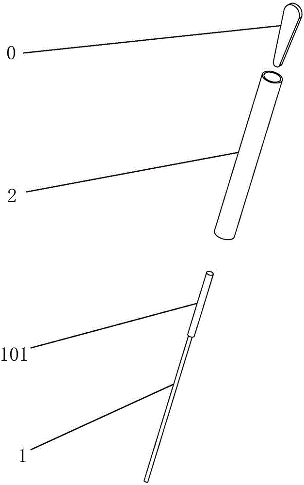
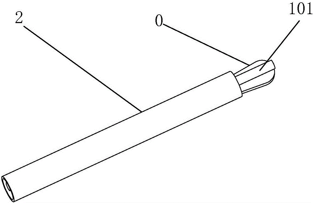
technical field [0001] The invention relates to the technical field of acupuncture needle through-tube packaging, more specifically, it relates to an automatic tube-through packaging machine. Background technique [0002] Modern acupuncture needles are generally composed of a needle body, a needle point and a needle handle. The front end of the needle body is the needle point, and the rear end is the needle handle. It can be lifted, inserted and twisted at any time, and acupuncture needles need to be packaged during production to facilitate transportation and storage; [0003] The most widely used packaging method at present is through the tube packaging method, such as figure 1 and figure 2 As shown, the specific implementation of this tube-through packaging is as follows: the acupuncture needle 1 is inserted into the plastic tube 2, and then a wedge-shaped plastic sheet 0 is inserted into one end of the plastic tube 2, and the tube and the needle are pressed tightly to ...

Claims


Application Information

Patent Timeline
Patent Type & Authority Applications(China)
IPC IPC(8): B65B5/04B65B35/10
CPCB65B5/04B65B35/10
Inventor 屠家凯
Owner 江苏凯邦医疗器械有限公司
Learn More