Annular flow guide gate for ship

A kind of diversion grid and annular technology, which is applied in the field of marine annular diversion grid, which can solve the problems of optimal adjustment of the angle and position of the upflow, and the resistance of the duct.

Inactive Publication Date: 2016-10-26
CSIC SHANGHAI MARINE ENERGY SAVING TECH DEV CO LTD
View PDF14 Cites 4 Cited by
  • Summary
  • Abstract
  • Description
  • Claims
  • Application Information

AI Technical Summary

Problems solved by technology

The duct of this device is a whole, so the upstream angle and position of the left and right sides of the duct cannot be optimized and adjusted according to the local flow field alone. Due to the inhomogeneity of the wake field at the stern, the duct of this device will generate large resistance

Method used


Image

  • Annular flow guide gate for ship
  • Annular flow guide gate for ship
  • Annular flow guide gate for ship

Examples


Embodiment 1

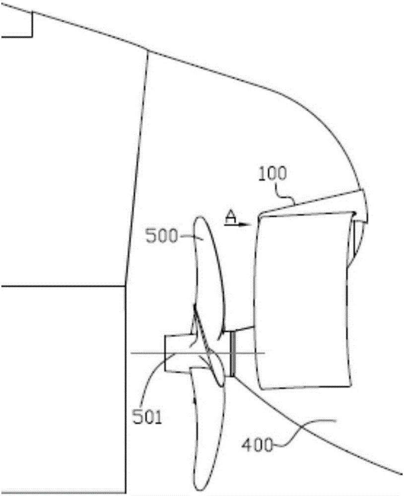
[0024] Example 1, such as figure 1 As shown, the device 100 of the present invention is fixedly installed in front of the propeller 500 and at the stern of the hull 400 , most of which are offset above the propeller shaft 501 .

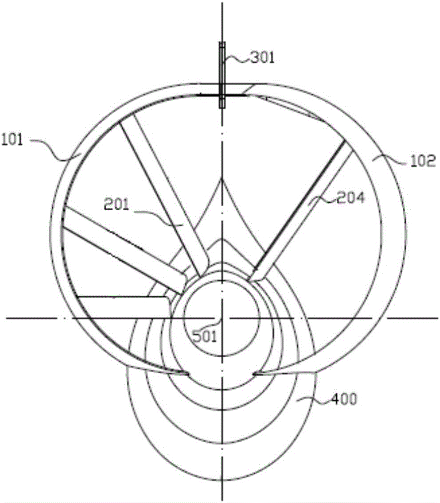
[0025] like figure 2 It is a detailed structural diagram of the present invention. The device 100 of the present invention comprises a port draft tube 101, a starboard draft tube 102, a port guide vane 201, a starboard guide vane 204 and a reinforcement structure 301, the lower ends of the port draft tube 101 and the starboard draft tube 102 are directly connected to the hull 400, The upper ends of the port draft tube 101 and the starboard draft tube 102 are connected through a reinforcement structure 301, and the reinforcement structure 301 is fixedly connected to the hull 400. They form an angle of 3° with each other in the horizontal direction. The quantity of the port guide vane 201 is determined according to the space inside the port guide va...

Embodiment 2

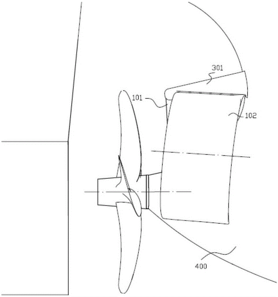
[0027] Example 2, such as image 3 Shown is another embodiment of the present invention. In this embodiment, the lengths of the port draft tube 101 and the starboard draft tube 102 are both 0.4 times the diameter of the propeller 500, and the diameters of the port draft tube 101 and the starboard draft tube 102 are both 0.6 times the diameter of the propeller 500. The port nozzle 101 has an inclination of -3° in the vertical plane, and the starboard nozzle 102 has an inclination of +3° in the vertical plane.

Embodiment 3

[0028] Example 3, such as Figure 4 As shown, the port draft tube 101 and the starboard draft tube 102 are semi-elliptical, the lengths of the port draft tube 101 and the starboard draft tube 102 are 0.25 times the diameter of the propeller 500, and the port draft tube 101 and the starboard draft tube The major axes of the flow tubes 102 are also 0.85 times the diameter of the propeller 500 . Wherein the long axis of the ellipse is along the up-down direction, and the short axis is along the horizontal direction.


PUM


Abstract

The invention provides an annular flow guide gate for a ship. The annular flow guide gate is characterized by comprising a left side flow guide pipe, a right side flow guide pipe, left side guide vanes and right side guide vanes; the upper end of the left side flow guide pipe and the upper end of the right side flow guide pipe are fixed to a hull through a reinforcing structure, and the lower end of the left side flow guide pipe and the lower end of the right side flow guide pipe are fixedly connected to the hull; one end of each left side guide vane is installed on the inner side of the left side flow guide pipe, and the other end of each left side guide vane is installed on the hull in the radial direction of a propeller; and one end of each right side guide vane is installed on the inner side of the right side flow guide pipe, and the other end of each right side guide vane is installed on the hull in the radial direction of the propeller. By the adoption of the annular flow guide gate, the wake flow field of the hull can be improved, the losses of the main machine output power are reduced, the efficiency of a thruster is improved, and the navigation speed of the ship is increased. The annular flow guide gate has the beneficial effects of being simple in structure and convenient to install.

Description

technical field [0001] The invention relates to a hydrodynamic energy-saving device in front of a propeller, in particular to a marine annular diversion grid. Background technique [0002] Fuel costs account for a major proportion of ship operating costs, and saving fuel consumption and reducing fuel costs are eternal pursuits of shipowners. At the same time, various environmental problems caused by greenhouse gas emissions are becoming more and more serious, and have received extensive attention from the international community. Therefore, green ship technology has become the top priority of industry research, and ship hydrodynamic energy-saving devices are gradually favored by shipowners. The current hydrodynamic energy-saving devices in front of the propeller include wake compensation ducts, rectifying fins, pre-rotation fins plus full ducts, and Mewis Duct. It has been gradually unable to apply to modern new ships whose stern line shape is getting smoother and thinner,...

Claims


Application Information

Patent Timeline
Patent Type & Authority Applications(China)
IPC IPC(8): B63H1/28
CPCB63H1/28
Inventor 黄树权郭峰山夏灏超吴赞陈雷强黄国富黄振宇董振庆
Owner CSIC SHANGHAI MARINE ENERGY SAVING TECH DEV CO LTD
Why Eureka
Try Eureka