
Cylinder body rack

A technology for placing racks and oil cylinders, which is applied in the field of oil cylinders, and can solve problems such as the cylinder body being susceptible to moisture, the cylinder body bumping, and sticky debris

Active Publication Date: 2018-05-11
WUXI YUANCHANG MACHINE MFG
View PDF6 Cites 0 Cited by
  • Summary
  • Abstract
  • Description
  • Claims
  • Application Information

AI Technical Summary

Problems solved by technology

However, when stacking cylinder blocks in general workshops, they are randomly stacked in the corners. Not only is it easy to accidentally bump the cylinder blocks during production, but also the cylinder blocks are prone to moisture and stick to debris and stains.

Method used


Image

  • Cylinder body rack

Examples


Embodiment Construction

[0013] The following will clearly and completely describe the technical solutions in the embodiments of the present invention. Obviously, the described embodiments are only some of the embodiments of the present invention, rather than all the embodiments. Based on the embodiments of the present invention, all other embodiments obtained by persons of ordinary skill in the art without making creative efforts belong to the protection scope of the present invention.

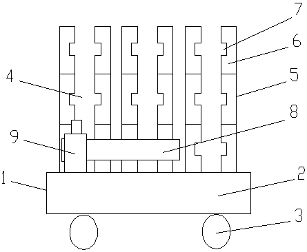
[0014] see figure 1 , the embodiment of the present invention includes:

[0015] An oil cylinder block placement frame, comprising a placement frame body 1, a floor seat 2 is provided at the lower end of the placement frame body 1, a roller mechanism 3 is installed at the bottom end of the floor seat 2, and a plurality of Oil cylinder block placement area 4, the oil cylinder block placement area 4 is surrounded by four vertical rods 5, and the vertical rods 5 are arranged at four corners of the oil cylinder block pl...


PUM


Abstract

The invention discloses an oil cylinder placing rack. The oil cylinder placing rack comprises a placing rack body. A base plate is arranged at the lower end of the placing rack body. An oil cylinder placing area is arranged at the upper end of the base plate. The oil cylinder placing area is formed by four vertical rods in an enclosed manner. The vertical rods are arranged at four corners of the oil cylinder placing area. Each vertical rod is formed by multiple splicing rods connected in a threaded manner. A plurality of support plate clamp grooves are formed in the inner-side rod bodies of the splicing rods. Oil cylinder support plates can be clamped into the support plate clamp grooves. A lubricant spraying pipe is further mounted at one end of the base plate. The lubricant spraying pipe is horizontally mounted on the upper-end plate surface of the base plate. By the arrangement, the oil cylinder placing rack has the advantages that the oil cylinder placing rack can be used for conveniently and stably placing oil cylinders, the oil cylinders can be stacked in the oil cylinder placing area, the space of the placing rack body is fully utilized, and the lubricant spraying pipe arranged on the placing rack body can lubricate the interior of the oil cylinder sleeving the lubricant spraying pipe.

Description

technical field [0001] The invention relates to the field of oil cylinders, in particular to an oil cylinder block placement frame. Background technique [0002] A hydraulic cylinder is a hydraulic actuator that converts hydraulic energy into mechanical energy and performs linear reciprocating motion. It has simple structure and reliable operation. When it is used to realize reciprocating motion, the deceleration device can be eliminated, and there is no transmission gap, and the motion is stable, so it is widely used in various mechanical hydraulic systems. The output force of the hydraulic cylinder is proportional to the effective area of ​​the piston and the pressure difference on both sides; the hydraulic cylinder is basically composed of a cylinder barrel and a cylinder head, a piston and a piston rod, a sealing device, a buffer device and an exhaust device. Buffers and exhausts are application specific and others are essential. However, when stacking cylinder blocks...

Claims


Application Information

Patent Timeline
Patent Type & Authority Patents(China)
IPC IPC(8): B25H3/04
CPCB25H3/04
Inventor 王伟唐志明
Owner WUXI YUANCHANG MACHINE MFG
Learn More