
Atomization control device and control method

A control device and smoke technology, which is applied to spray devices, liquid spray devices, etc., can solve the problems of large temperature fluctuation range, inability to carry around, and large size of the fog machine, and achieves small temperature fluctuation range, good atomization effect, and controllable Accurate effect

Active Publication Date: 2016-10-26
QINGDAO LINGDING TECH
View PDF7 Cites 2 Cited by
  • Summary
  • Abstract
  • Description
  • Claims
  • Application Information

AI Technical Summary

Problems solved by technology

[0002] At present, due to the existence of non-linear characteristics such as large inertia, large time variation, and pure hysteresis of the heating wire, the traditional smoke electromechanical heating technology mainly uses no feedback or the temperature switch cuts off the power supply of the control relay to achieve the purpose of changing the heating power output. The traditional smoke The fog machine has the following technical problems: on the one hand, the fog machine is affected by the error of the instrument itself and the electrical life of the temperature switch, the on-off frequency is low, and the temperature fluctuation range is large; on the other hand, the traditional fog machine has a large volume and needs to be used in practical applications AC voltage power supply, at the same time, the traditional smoke machine needs to be warmed up before it can be used normally, and cannot be carried around

Method used


Image

  • Atomization control device and control method
  • Atomization control device and control method
  • Atomization control device and control method

Examples


Embodiment

[0050] The smoke adjustment and temperature adjustment process of the PIC single-chip microcomputer are illustrated below in conjunction with the embodiments

[0051] The operating parameters of the PIC single-chip microcomputer are as follows: the proportional parameter of the built-in PID regulator of the PIC chip is P, and the initial value of the integral time of the PID regulator parameter is I. The PIC chip is connected with the display, and the display displays the temperature data collected by the temperature sampling circuit in real time, and the temperature data Real-time display through temperature curve.

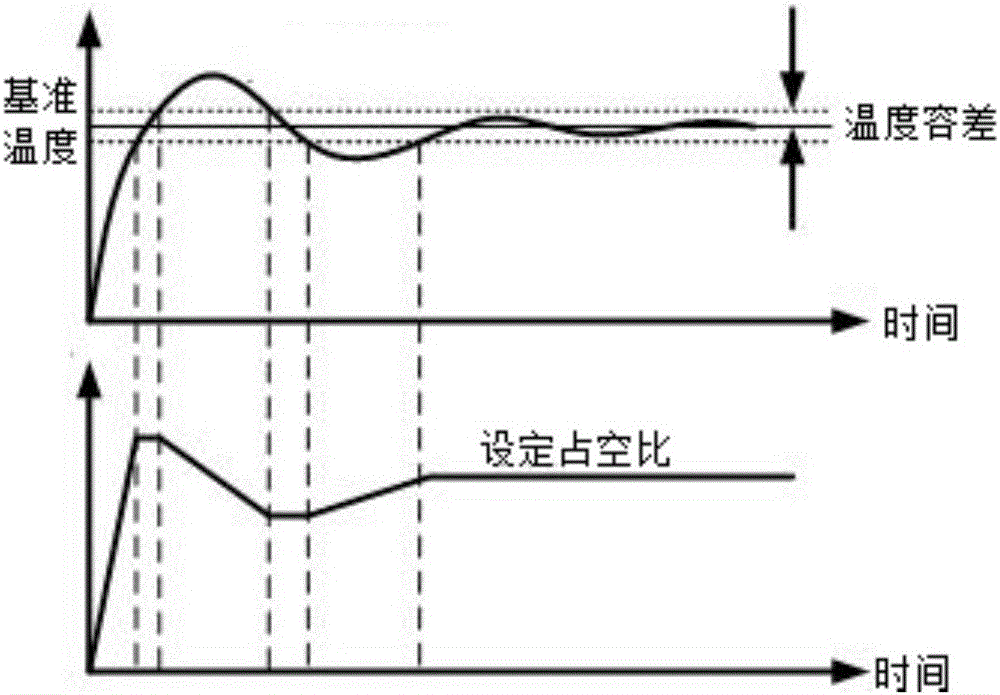
[0052] At first, carry out the debugging of proportional parameter P, set the initial value of PID parameter I as infinity, concrete experiment is set to 9999 with I, d=0, P=1, makes PID become a pure proportional algorithm, changes P numerical value this moment, Observing the temperature sampling circuit through the display to collect the collected temperature d...


PUM


Abstract

The invention discloses an atomization control device and a control method. The atomization control device comprises a PIC (Peripheral Interface Controller) single chip microcomputer, a temperature sampling circuit, an oil pump driving circuit and an electrical heated tube driving circuit, wherein the temperature sampling circuit, the oil pump driving circuit and the electrical heated tube driving circuit are all connected with the PIC single chip microcomputer; the temperature sampling circuit is further connected with the electrical heated tube driving circuit; the electrical heated tube driving circuit comprises an electrical heated tube with a heating wire arranged therein; the temperature sampling circuit acquires the temperature of the heating wire and feeds the temperature of the heating wire back to the PIC single chip microcomputer; the PIC single chip microcomputer conducts pulse width adjustment via PWM (Pulse-Width Modulation) and outputs power to the electrical heated tube driving circuit through a pin; the heating wire is quickly heated up to a reference temperature; the PIC single chip microcomputer drives an oil pump to work through the oil pump driving circuit; the oil pump pumps a smoke agent through a pipeline and transmits the smoke agent into the electrical heated tube; then the smoke agent is heated and quickly expanded and atomized; smoke is sprayed via the orifice of the electrical heated tube; and the PIC single chip microcomputer adjusts the PWM duty cycle through an internal PID (Proportion Integration Differentiation) regulator to further adjust the output power.

Description

technical field [0001] The invention relates to the technical field of atomization equipment, in particular to an atomization control device and a control method. Background technique [0002] At present, due to the existence of non-linear characteristics such as large inertia, large time variation, and pure hysteresis of the heating wire, the traditional smoke electromechanical heating technology mainly uses no feedback or the temperature switch cuts off the power supply of the control relay to achieve the purpose of changing the heating power output. The traditional smoke The fog machine has the following technical problems: on the one hand, the fog machine is affected by the error of the instrument itself and the electrical life of the temperature switch, the on-off frequency is low, and the temperature fluctuation range is large; on the other hand, the traditional fog machine has a large volume and needs to be used in practical applications AC voltage power supply, at th...

Claims


Application Information

Patent Timeline
Patent Type & Authority Applications(China)
IPC IPC(8): B05B9/00B05B9/04B05B12/02
CPCB05B9/002B05B9/0403B05B12/02
Inventor 赵善祥赵学宽赵光亮刘玉彦
Owner QINGDAO LINGDING TECH
Learn More