
Cables and Antennas

A cable and antenna technology, applied in the direction of the antenna grounding switch structure connection, electrical components, connections, etc., can solve the problems of increased risk of passive intermodulation effect of integrated antennas, difficult to replace and maintain, and avoid thermal cascades. effect, ease of replacement and repair, effect of reducing PIM risk

Active Publication Date: 2019-03-08
中资铁塔股份有限公司
View PDF2 Cites 0 Cited by
  • Summary
  • Abstract
  • Description
  • Claims
  • Application Information

AI Technical Summary

Problems solved by technology

[0005] The invention provides a cable and an antenna, which are used to solve the technical problems in the prior art that the risk of passive intermodulation effect of the integrated antenna is increased and it is not easy to replace and maintain

Method used


Image

  • Cables and Antennas
  • Cables and Antennas
  • Cables and Antennas

Examples


Embodiment Construction

[0055] In order to make the purpose, technical solutions and advantages of the embodiments of the present invention clearer, the technical solutions in the embodiments of the present invention will be clearly and completely described below in conjunction with the drawings in the embodiments of the present invention. Obviously, the described embodiments It is a part of embodiments of the present invention, but not all embodiments. Based on the embodiments of the present invention, all other embodiments obtained by persons of ordinary skill in the art without creative efforts fall within the protection scope of the present invention.

[0056] The cable of the present invention can be applied to the transmission of signals between communication devices in a communication system, such as the signal transmission between the antenna unit of an integrated antenna in a base station antenna feeder system and a radio frequency unit or other communication units. For the convenience of des...


PUM


Abstract

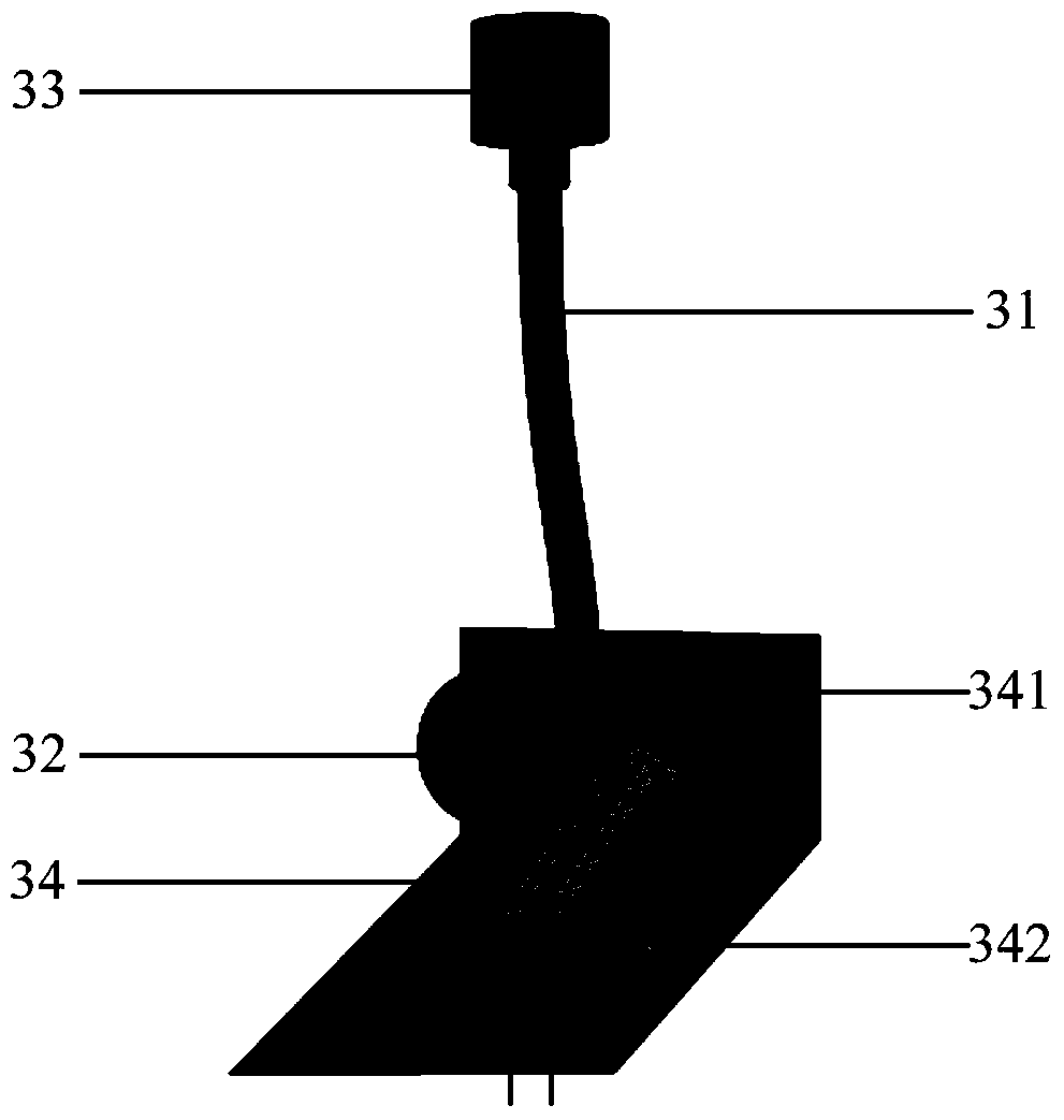
The invention provides a cable and an antenna. The cable comprises a cable body, a first connector and a second connector. The first connector and the second connector are arranged on two ends of the cable body respectively. The first connector is provided with an insulation wind guiding plate. The insulation wind guiding plate comprises a fixing portion and a wind guiding portion. The fixing portion is used for fixing the insulation wind guiding plate to the first connector. The wind guiding portion is connected to the fixing portion. The wind guiding portion and the fixing portion form an included angle. The first connector is located in a scope of the included angle and the included angle is less than 180 degree. By using the cable and the antenna provided in an embodiment of the invention, a thermal cascade effect can be effectively avoided; a PIM risk is reduced; and plugging and waterproof operation spaces of the cable do not need to be occupied so that replacing and maintenance of antenna components are easy to operate.

Description

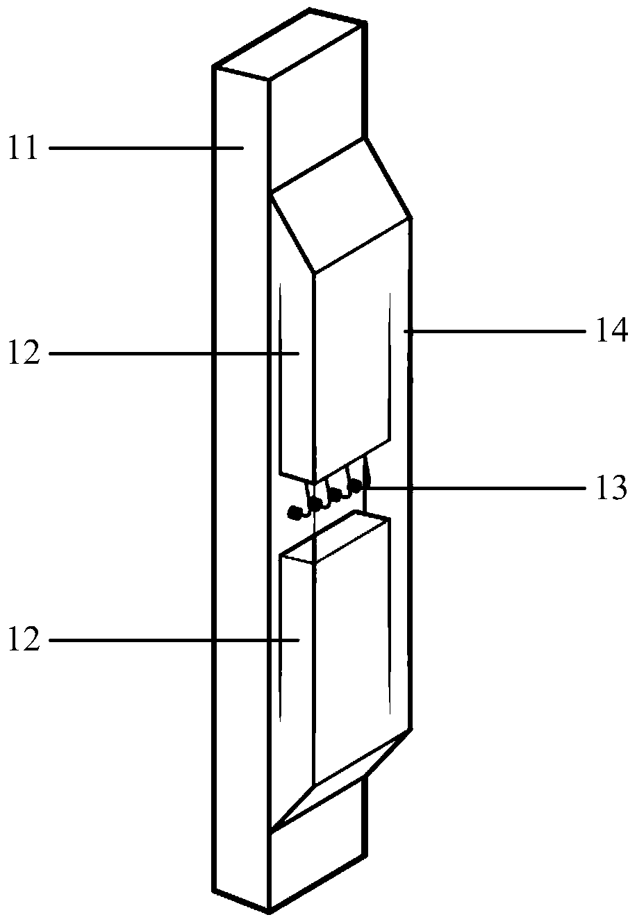
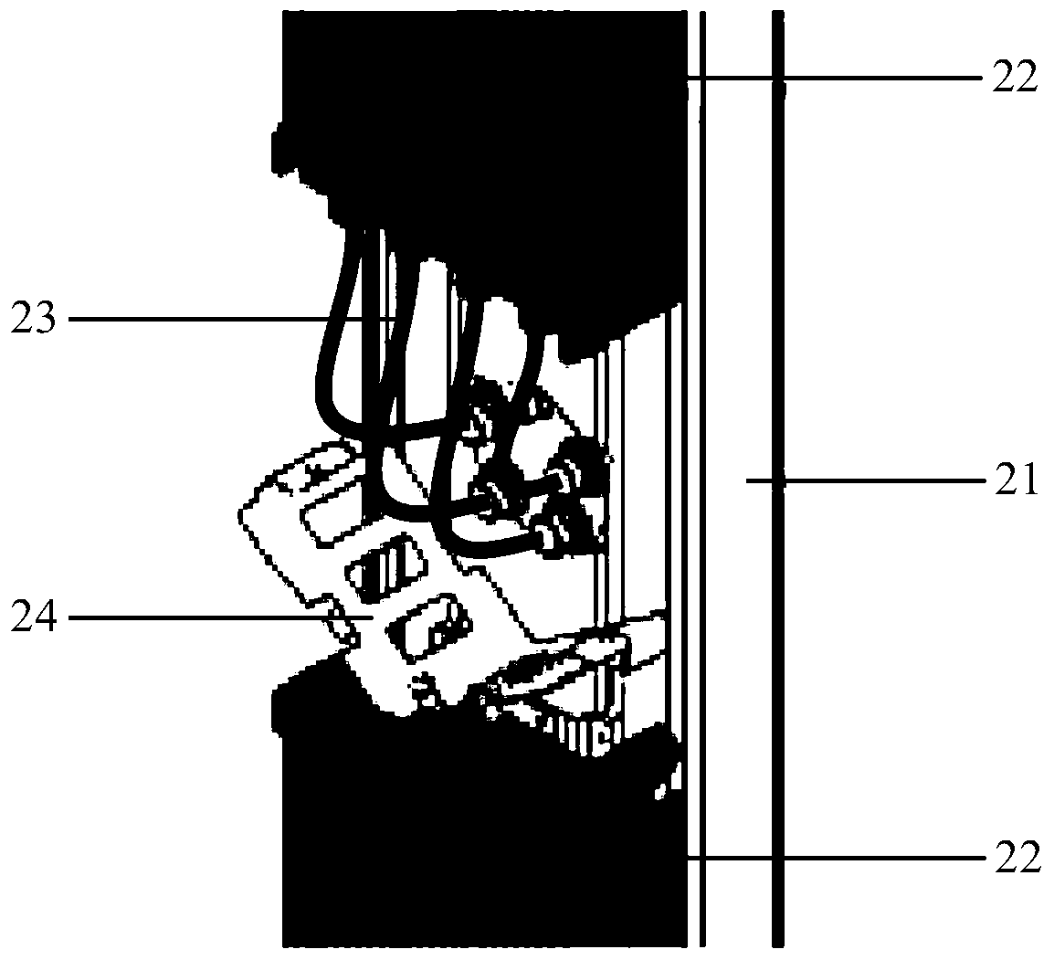
technical field [0001] The invention relates to the technical field of communication, in particular to a cable and an antenna. Background technique [0002] Integrated antenna as a new type of wireless device, such as figure 1 As shown, one antenna unit 11 and multiple radio frequency units 12 are integrated, and the antenna unit 11 and the radio frequency units 12 are connected by radio frequency cables 13 . Each radio frequency unit 12 generally has a natural heat dissipation structure, and due to the need for beautification, the radio frequency unit area of ​​the existing antenna is provided with a beautification cover 14, and the layout of each radio frequency unit 12 is compact, so there is a cascade of heat dissipation between the upper and lower radio frequency units 12. The problem is that the hot air emitted by the lower radio frequency unit 12 will enter the heat dissipation area of ​​the upper radio frequency unit 12 , resulting in deterioration of the heat dissi...

Claims


Application Information

Patent Timeline
Patent Type & Authority Patents(China)
IPC IPC(8): H01Q1/50H01R9/03
Inventor 金庆浩郑明辉王提政
Owner 中资铁塔股份有限公司
Learn More