
Vehicle positioning device

A vehicle positioning and vehicle technology, applied in the field of navigation, can solve problems such as misjudgment and reduce positioning reliability, and achieve the effect of improving reliability and ensuring accuracy

Inactive Publication Date: 2016-10-19
FAURECIA CLARION ELECTRONICS (XIAMEN) CO LTD
View PDF1 Cites 12 Cited by
  • Summary
  • Abstract
  • Description
  • Claims
  • Application Information

AI Technical Summary

Problems solved by technology

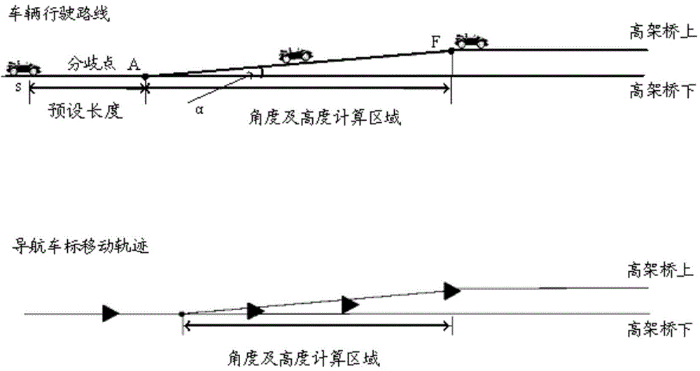
For example, when a vehicle passes through a section of road with a certain slope and then passes through a viaduct, and the distance between the road with a slope and the viaduct is relatively close, because there is no distinction between the road with a slope ahead and the viaduct, the existing technology is very difficult It may be judged that the sloped road is a viaduct, which may cause misjudgment and reduce the reliability of positioning

Method used


Image

  • Vehicle positioning device
  • Vehicle positioning device
  • Vehicle positioning device

Examples


Embodiment 1

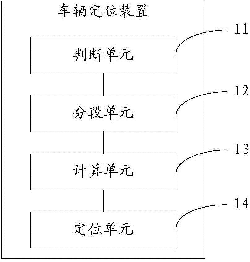
[0039] Such as figure 2 As shown, in order to improve the reliability of vehicle positioning, Embodiment 1 of the present invention provides a vehicle positioning device, which includes a judging unit 11, a segmentation unit 12, a computing unit 13 and a positioning unit 14. The following describes the device The functions of each unit are described in detail.

[0040] judgment unit

[0041] The judging unit 11 is configured to detect whether there is a divergence point ahead of the vehicle according to the navigation information of the vehicle, and the divergence point is a separation point of an uphill road and a horizontal road in the same direction at the viaduct.

[0042] Wherein, for the judging unit 11, the navigation information here mainly refers to map information, through which it can be determined whether there is a branch point in front of the vehicle, and then it can be determined whether the vehicle is in front of a road with a slope or a viaduct. According...

Embodiment 2

[0066] The vehicle positioning device provided in the second embodiment is basically the same in structure and function as the vehicle positioning device provided in the first embodiment above, so the following only introduces the differences between the two, and for the similarities between the two, refer to the implementation Introduction to Example 1.

[0067] The calculation unit 13 of the vehicle positioning device in this embodiment can correct the calculated height h of the vehicle. It has been known from the first embodiment above that when the vehicle is positioned on or under the viaduct, the road height H determined according to the navigation information is usually inaccurate, and its reliability is not high. On the other hand, since the height h of the vehicle is calculated based on the elevation angle detected by the vehicle's own three-axis gyroscope, and the sensitivity and accuracy of the three-axis gyroscope itself are low, the calculated vehicle The height ...


PUM


Abstract

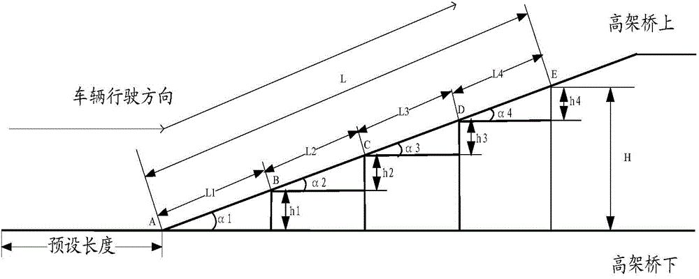
The embodiment of the invention discloses a vehicle positioning device, and relates to the technical field of navigation, and aims to improve the reliability of vehicle positioning. The device includes the following parts: a judgment unit, which is used for detecting whether there is a bifurcation point ahead the vehicle according to the vehicle navigation information; a segmentation unit, which is used for segmenting a preset distance L, which is for the vehicle to pass by and has the bifurcation point as the starting point, if the judgment unit determines there is a bifurcation point ahead the vehicle; a calculation unit, which is used for calculating an increased height hi of the end point relative to the starting point of each distance divided by the segmentation unit, and summing up the height hi corresponding to each distance to obtain a height h corresponding to the preset distance; a positioning unit, which is used for comparing current height h of the vehicle with a road height H corresponding to the preset distance determined by the vehicle navigation information, and positioning the vehicle on or under a viaduct according to the comparison result. The invention is used for vehicle positioning.

Description

technical field [0001] The invention relates to the technical field of navigation, in particular to a vehicle positioning device. Background technique [0002] At present, the navigation system is generally used to navigate the vehicle, and in some cases, it is necessary to accurately locate the position of the vehicle to prevent the vehicle from taking the wrong route. For example, when a vehicle passes a viaduct, a navigation device is required to accurately locate whether the vehicle is on the viaduct or under the bridge, so as to avoid the occurrence of the above situation. However, the positioning accuracy of current navigation devices is relatively low. The patent document with the publication number of JP-A-2008-76389 discloses a navigation device which combines an inertial navigation system with a satellite navigation system to locate the position of the vehicle, which can improve the positioning accuracy to a certain extent. [0003] In the process of realizing th...

Claims


Application Information

Patent Timeline
IPC IPC(8): G01C21/34
Inventor 庄祖铭吴慰娜王志威
Owner FAURECIA CLARION ELECTRONICS (XIAMEN) CO LTD
Learn More