
Terminal structure for superconducting cable and method for manufacturing same

A technology of superconducting cables and structures, which is applied in the direction of cable/conductor manufacturing, usage of superconductor elements, superconducting devices, etc. It can solve the problems of connection resistance deviation, cumbersome, and cumbersome production of normally conductive connecting parts, etc., to reduce The effect of contact resistance

Active Publication Date: 2016-10-12
SHOWA ELECTRIC WIRE & CABLE CO
View PDF10 Cites 7 Cited by
  • Summary
  • Abstract
  • Description
  • Claims
  • Application Information

AI Technical Summary

Problems solved by technology

Thus, for the structure of connecting the superconducting tape to the connection surface of the outer surface of the electrode, it is necessary to accurately match the outer diameter of the connection surface of the outer surface with the outer diameter of the layer of the corresponding superconducting tape, with the connection surface The production of the normal conductor connecting parts is relatively cumbersome
In addition, during the assembly operation of the terminal structure, it is necessary to pay attention to the accurate connection between the superconducting strips of each layer and the connection surface of the corresponding normal-conducting connection parts at each layer, which is cumbersome.
In addition, in the case where these connections are performed one by one by manual operation, there is a problem that the connection resistance values ​​at the connection portions are prone to vary.

Method used


Image

  • Terminal structure for superconducting cable and method for manufacturing same
  • Terminal structure for superconducting cable and method for manufacturing same
  • Terminal structure for superconducting cable and method for manufacturing same

Examples


Embodiment 1

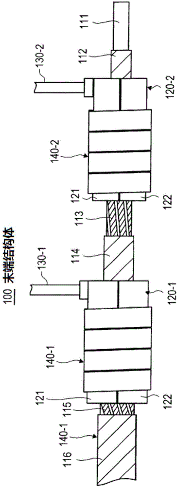
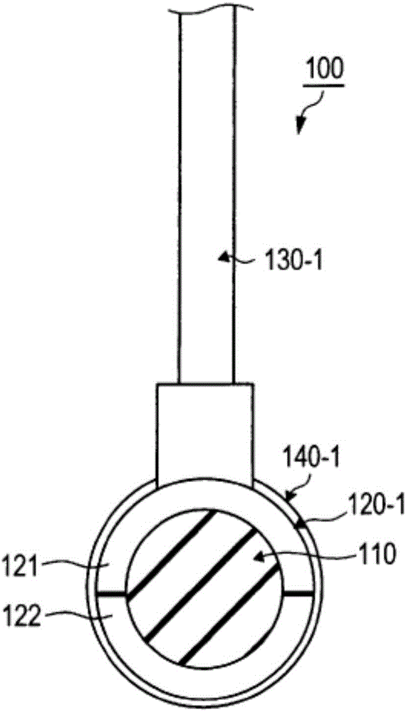
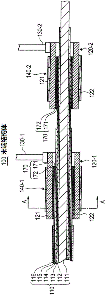
[0117] Formed with thickness 0.12[mm]×width 5[mm] Figure 5 REBa shown y Cu 3 o z It is a superconducting wire, and 10 superconducting wires are wound around the core material to form each layer of a superconducting tape to form a superconducting cable. Using the superconducting cable, cylindrical electrodes, and diameter-reducing parts, the above-mentioned structure is produced. End structure 100 . The inner surface of the cylindrical electrode 120 - 1 and the outer peripheral surface (surface on the substrate side) of the superconducting tape 115 are connected by solder 170 . In addition, when the tubular electrode 120 is connected to the superconducting strip 115, pre-solder portions 171 and 172 are provided on the connection surfaces of the two, such as Figure 9 ~ Figure 14 They were fabricated as shown.


PUM

PropertyMeasurementUnit
thicknessaaaaaaaaaa
widthaaaaaaaaaa

Abstract

Provided is a terminal structure for a superconducting cable that causes an electrode and a superconducting cable to be easily and favorably connected with reduced contact resistance. In the superconducting cable, a superconducting wire in which a superconducting layer is provided on a substrate interposed by an intermediate layer is wound around a core so that the superconducting layer becomes the inner periphery side and the substrate becomes the outer periphery side. In the terminal structure, the superconducting cable (110) has a plurality of superconducting wires (113, 115), in which a superconducting layer is provided on the substrate interposed by an intermediate layer, and the plurality of superconducting wires (113, 115) are arranged in multiple layers so as to be wound concentrically around a core (111) so that the superconducting layer becomes the inner periphery side and the substrate becomes the outer periphery side. The superconducting cable (110) is arranged inside a tubular electrode (120) and the inner surface of the tubular electrode (120) is soldered to the substrate-side surface of, among the plurality of superconducting wires (113, 115), the superconducting wire (113, 115) positioned at the outermost layer inside the tubular electrode (120).

Description

technical field [0001] The present invention relates to an end structure of a superconducting cable, and in particular, to an end structure of a superconducting cable in which a superconducting layer of a superconducting wire having a superconducting layer is spirally wound inside the cable. Background technique [0002] Conventionally, in a superconducting cable, a tape-shaped superconducting wire (hereinafter also referred to as “superconducting tape”) is wound helically around the outer periphery of a core material (former). In addition, in superconducting cables, superconducting tapes are usually arranged concentrically in multiple layers in order to transmit large currents. A pressure belt is provided between layers of superconducting tapes arranged in multiple layers (that is, between superconducting tapes), and the pressure tape presses the superconducting tapes and electrically insulates between the superconducting tapes. In addition, as a superconducting tape, REBa...

Claims


Application Information

Patent Timeline
Patent Type & Authority Applications(China)
IPC IPC(8): H01R4/68H01B7/00H01B12/06H01B13/00H01R43/02
CPCH01R4/01H01R4/024H01R4/68H02G15/34Y02E40/60
Inventor 北村祐中西达尚引地康雄
Owner SHOWA ELECTRIC WIRE & CABLE CO
Learn More