
Safe socket with protective cover plate

A technology of protective cover and safety socket, which is applied to parts, electrical components, coupling devices, etc. of connecting devices, which can solve problems such as difficult to repair, thick connection between wires and plugs, and damages.

Inactive Publication Date: 2016-10-12
芜湖龙峰电器电子有限公司
View PDF5 Cites 1 Cited by
  • Summary
  • Abstract
  • Description
  • Claims
  • Application Information

AI Technical Summary

Problems solved by technology

[0003] The positions of the jacks on the existing sockets are fixed regardless of the positions of the two-hole jacks or the three-hole jacks, especially the fixed three-hole jacks will cause the following inconveniences during use: in order to improve the strength of the plug, it is necessary to prevent repeated plugging. Use deformation to prolong the service life. The three-prong plug of the electrical appliance is bulky and the connection between the wire and the plug is thick and hard. When in use, the wire connected to the plug can only extend in one direction, for example, it can only be vertically upward Under the condition of narrow space, the wires at the connection will be bent or twisted under a large force. Such a long-term restraint will cause the wires to break inside and lose the function of connecting electrical appliances.
[0004] At the same time, the exposed jacks are easy to cause children to touch and cause electric shock accidents, causing irreparable damage
Moreover, children's curiosity drives them to pull out the plug that has been inserted in the socket. If the plug is easily pulled off, the socket in use will be exposed again, and there is still a risk of electric shock.

Method used


Image

  • Safe socket with protective cover plate

Examples


Embodiment Construction

[0033] Specific embodiments of the present invention will be described in detail below in conjunction with the accompanying drawings. It should be understood that the specific embodiments described here are only used to illustrate and explain the present invention, and are not intended to limit the present invention.

[0034] In the present invention, in the absence of a contrary description, the orientation words included in the term such as "top, inner wall" only represent the orientation of the term in the normal use state, or the common name understood by those skilled in the art, and should not be viewed as a limitation of this term.

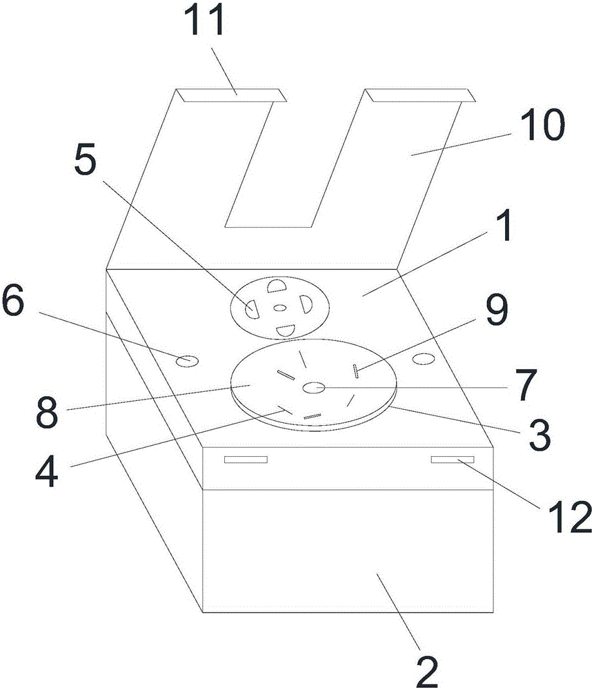
[0035] see figure 1 , the present invention provides a safety socket with a protective cover, which is composed of a socket plate 1, a socket box 2 and a rotating piece 3; wherein,

[0036] There is an opening on the socket box 2, and the socket plate 1 is covered on the opening and is detachably fixed to the socket box 2 so that a cavity...


PUM


Abstract

The invention discloses a safe socket with a protective cover plate. An opening is arranged in a socket box, and a socket plate covers the opening and is provided with a through hole. One end of a rotary shaft is fixedly connected on the bottom wall of the socket box, and the other end extends and penetrates through the through hole to connect with a rotary sheet. Three socket holes are arranged in the rotary sheet which is sleeved inside a sleeving hole and can spin. A rotary cover covers the rotary sheet and is provided with three bar-shaped holes matching with the three socket holes. The rotary cover can rotate coaxially with the rotary sheet to expose or cover the three bar-shaped holes, and the protective cover plate is arranged on the socket plate. One end of the protective cover plate is hinged to one side edge of the socket plate, and the other end of the protective cover plate is provided with a buckle. A gap is arranged in the direction from the buckle to the hinge. The gap is smaller than the cross section of a plug and greater than the cross section of a connecting wire on the plug. The protective cover plate rotates, so that the buckle matches with a buckle groove, the protective cover plate is fixed and a wire extends out from the gap. The safe socket has the advantages of simple structure, convenient use and high use safety, and electric shock accidents of children randomly plugging plugs can be prevented.

Description

technical field [0001] The present invention relates to electrical switchgear, in particular to a safety socket with a protective cover. Background technique [0002] Socket refers to the insertable seat of one or more circuit connections, can insert various wiring by it, is convenient to connect with other circuits. Through the connection and disconnection between the line and the copper parts, the final connection and disconnection of the part of the circuit is achieved. [0003] The positions of the jacks on the existing sockets are fixed regardless of the positions of the two-hole jacks or the three-hole jacks, especially the fixed three-hole jacks will cause the following inconveniences during use: in order to improve the strength of the plug, it is necessary to prevent repeated plugging. Use deformation to prolong the service life. The three-prong plug of the electrical appliance is bulky and the connection between the wire and the plug is thick and hard. When in use,...

Claims


Application Information

Patent Timeline
Patent Type & Authority Applications(China)
IPC IPC(8): H01R13/453H01R13/639H01R35/00
CPCH01R13/4532H01R13/639H01R35/00
Inventor 庄秀平
Owner 芜湖龙峰电器电子有限公司
Learn More