
Level transfer circuit, driving method thereof, grid drive circuit and display device

A technology for transferring circuits and levels, which is applied in the direction of logic circuit connection/interface layout, logic circuit, logic circuit coupling/interface using field effect transistors, etc., which can solve the problems of large energy consumption, low level conversion efficiency, and large occupied area And other issues

Active Publication Date: 2016-10-12
BOE TECH GRP CO LTD +1
View PDF4 Cites 6 Cited by
  • Summary
  • Abstract
  • Description
  • Claims
  • Application Information

AI Technical Summary

Problems solved by technology

[0003] The level shifting circuit is provided with an energy storage element, and the level shifting circuit of the prior art usually uses an inductor as an energy storage element, and uses a diode in conjunction with it, which leads to a large number of electronic components in the circuit, a large occupied area, and relatively high energy consumption. Large, low level conversion efficiency

Method used


Image

  • Level transfer circuit, driving method thereof, grid drive circuit and display device
  • Level transfer circuit, driving method thereof, grid drive circuit and display device
  • Level transfer circuit, driving method thereof, grid drive circuit and display device

Examples


Embodiment Construction

[0034] Specific embodiments of the present invention will be described in detail below in conjunction with the accompanying drawings. It should be understood that the specific embodiments described here are only used to illustrate and explain the present invention, and are not intended to limit the present invention.

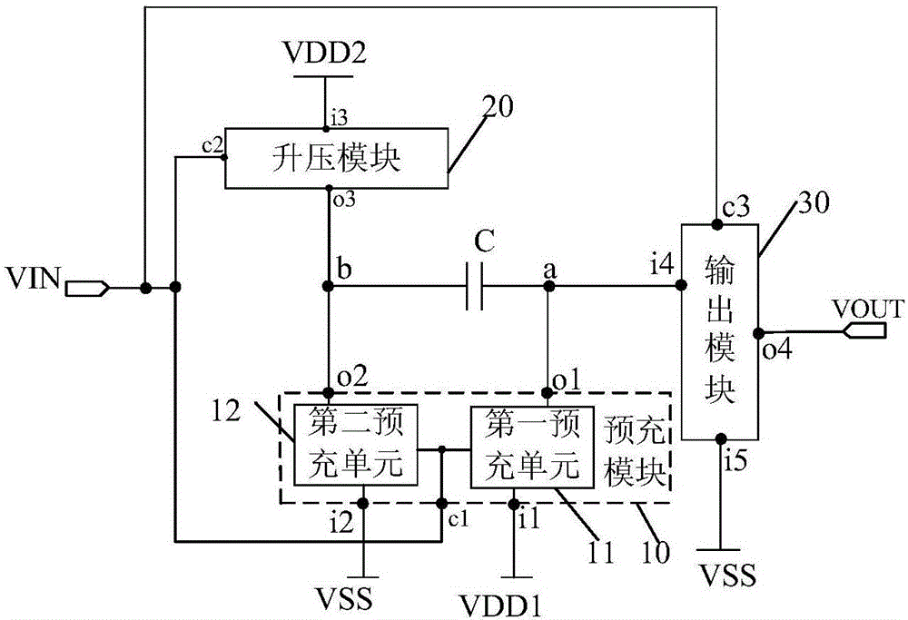
[0035] As an aspect of the present invention, a level shift circuit is provided, such as figure 1 As shown, it includes a signal input terminal VIN, a first high-level input terminal VDD1, a second high-level input terminal VDD2, a low-level input terminal VSS, a pre-output terminal a, a storage capacitor C, a pre-charge module 10 and a booster Module 20.

[0036] The first terminal of the storage capacitor C is connected to the pre-output terminal a.

[0037]The control terminal c1 of the pre-filling module 10 is connected to the signal input terminal VIN of the level shift circuit, the first input terminal i1 of the pre-filling module 10 is connected to the ...


PUM


Abstract

The invention provides a level transfer circuit. The level transfer circuit comprises a signal input end, a first high-level input end, a second high-level input end, a low-level input end, a pre-output end, a storage capacitor, a pre-charging module and a boost module; a first end of the storage capacitor is connected with the pre-output end, the control end of the pre-charging module is connected with the input end of the level transfer circuit, a first input end is connected with the input end of the first high-level input end, a second input end is connected with the low-level input end, a first output end is connected with a first end of the storage capacitor, a second output end is connected with the second end of the storage capacitor, the control end of the boost module is connected with the input end of the level transfer circuit, the input end is connected with the second high-level input end, and the output end is connected with the second end of the storage capacitor. The invention further provides a driving method of the level transfer circuit, a grid drive circuit and a display device. The level transfer circuit can improve boost efficiency.

Description

technical field [0001] The invention relates to the field of display technology, in particular to a level transfer circuit, a driving method thereof, a gate driving circuit and a display device. Background technique [0002] Thin film transistor liquid crystal display devices have received wide acclaim for their features such as good display quality, low voltage, low power consumption, and fast response. The display device includes an array substrate provided with an array of thin film transistors. When displaying, scan signals are sequentially provided to each row of gate lines through a shift register, so that the thin film transistors of each row are sequentially turned on. The turn-on voltage required by the thin film transistor is relatively high, but the output voltage of the shift register is relatively low, which cannot meet the requirement for turning on the switch of the thin film transistor. For this reason, a level shifter circuit is usually used to convert the ...

Claims


Application Information

Patent Timeline
IPC IPC(8): G09G3/36H03K19/0185
CPCG09G3/3677H03K19/018507
Inventor 刘宝玉孙志华
Owner BOE TECH GRP CO LTD
Learn More