
A sliding-form flexible platform device suitable for manoeuvring

A platform device and mold flexibility technology, which is applied in the field of sliding-form flexible platform device, can solve the problems of inability to achieve circular economy green construction, low value, and many auxiliary materials for equipment, etc. The effect of construction organization

Active Publication Date: 2018-06-29
CHINA MCC17 GRP
View PDF5 Cites 0 Cited by
  • Summary
  • Abstract
  • Description
  • Claims
  • Application Information

AI Technical Summary

Problems solved by technology

The overall structure of the conventional sliding form platform is reliable and has a wide range of applications, but the amount of welded steel bars is large, and the removed steel bars can no longer be used; at the same time, the wooden springboard of the sliding form platform is large in size but low in value. High dispatch cost
For silo slipform construction, the use of conventional slipform operation platform construction requires a lot of equipment and auxiliary materials, and the deployment cost is high, and it cannot meet the requirements of circular economy and green construction, which greatly restricts the efficiency of slipform construction and increases slipform construction cost

Method used


Image

  • A sliding-form flexible platform device suitable for manoeuvring
  • A sliding-form flexible platform device suitable for manoeuvring

Examples


Embodiment Construction

[0019] The technical solutions in the embodiments of the present invention will be clearly and completely described below in conjunction with the accompanying drawings in the embodiments of the present invention. Obviously, the described embodiments are only some of the embodiments of the present invention, not all of them. Based on The embodiments of the present invention and all other embodiments obtained by persons of ordinary skill in the art without making creative efforts belong to the protection scope of the present invention.

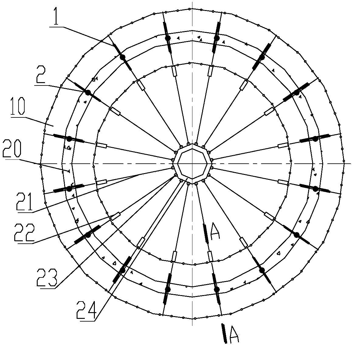
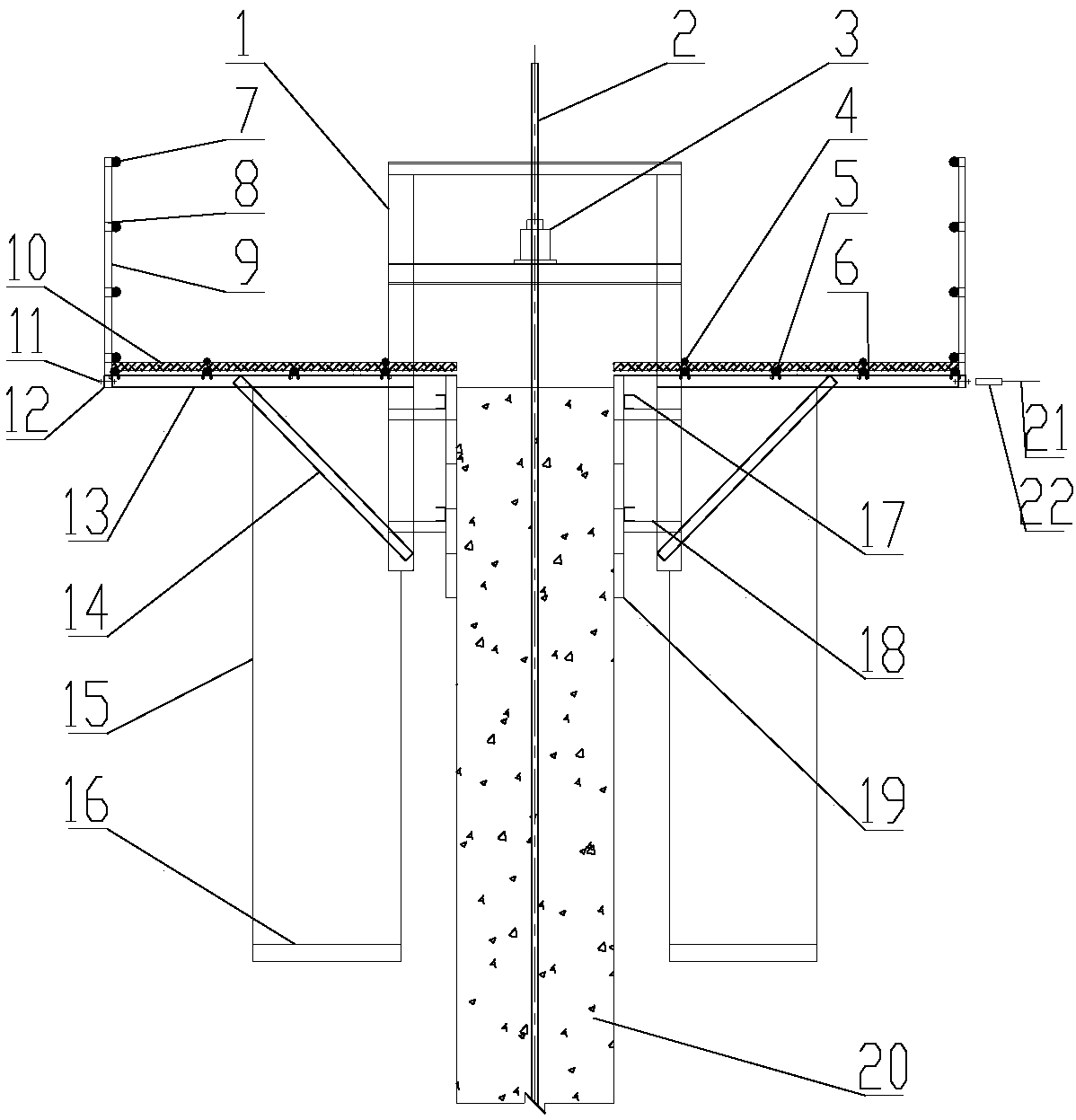
[0020] Depend on figure 1 and figure 2 It can be seen that a sliding form flexible platform device suitable for dispatching, during assembly, holes are drilled on the upper flange of the cantilever beam 13 on both sides of the lifting frame 1, and the hoop steel bars 5 are fastened to the cantilever beam by using U-shaped bolts 6 13, then lay square timber 10 on the hoop reinforcing bar 5, square timber 10 is compressed on the hoop reinforcing...


PUM


Abstract

The invention discloses a slip-form flexible platform device suitable for assigning. The slip-form flexible platform device comprises a plurality of lifting frames. Holes are drilled in the upper flanges of cantilever beams on the two sides of each lifting frame respectively, circumferential reinforcements are fastened to the cantilever beams through U-shaped bolts, timber is laid on the circumferential reinforcements and tightly pressed on the circumferential reinforcements through strip pressing reinforcements to form an operating platform, and the strip pressing reinforcements and the circumferential reinforcements are bound through iron wires; sleeves are welded to the ends of the cantilever beams, holes are drilled in the portions where the sleeves are connected with steel-tube stand columns, stand column steel tubes are fixed into the sleeves through bolts, and horizontal reinforcements of protecting barriers are buckled to the stand column steel tubes through right-angle fasteners; the lifting frames are tied through the steel wire ropes, and the steel wire ropes are connected at the centers of siloes through shackles and center circles. Amortizing of slip-form equipment, material consumption and assigning cost are reduced, construction cost is reduced, and meanwhile the repeated, economical and green construction requirements are met.

Description

technical field [0001] The invention belongs to the field of building construction, and in particular relates to a sliding form flexible platform device suitable for deployment in building construction. Background technique [0002] The silo slipform construction has the advantages of high degree of mechanization, good concrete continuity, saving the materials required for formwork support and scaffolding, convenient dismantling of the formwork, flexible assembly and reusability, etc. Therefore, the silo slipform construction Low cost and high construction efficiency. The sliding form construction period of the single silo is relatively short, and the construction of the sliding form platform from assembly to dismantling is generally only about one and a half months. After the sliding form construction is completed, it is often necessary to dispatch the sliding form equipment to enter the next project construction. While the conventional sliding form operation platform need...

Claims


Application Information

Patent Timeline
Patent Type & Authority Patents(China)
IPC IPC(8): E04G11/22E04H7/26
CPCE04G11/22E04H7/26
Inventor 王芝保
Owner CHINA MCC17 GRP
Learn More