High-temperature reaction device and graphene material production system
A high-temperature reaction and silo technology, applied in the chemical industry, can solve problems such as insufficient atmosphere control, difficulty in controlling the reaction time, and incomplete reaction
- Summary
- Abstract
- Description
- Claims
- Application Information
AI Technical Summary
Problems solved by technology
Method used
Image
Examples
Embodiment 1
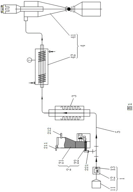
[0056] Example 1: rapid pyrolysis in high temperature inert atmosphere.
[0057] The feed bin 21 is opened, and the powder material to be pyrolyzed is added into the feed bin 21 . Then the silo 21 is evacuated, and then the inert gas required by the system is blown in from the discharge port 221 of the discharge machine 22 and the air inlet of the silo 21 . Reciprocate 2-3 times to complete the atmosphere replacement of the system.
[0058] Then turn on the high-temperature tube furnace and begin to heat up to the specified temperature required for the reaction. After the specified temperature is reached, the water inlet and outlet of the cooling mechanism 42 are opened to reduce the outlet gas temperature of the high-temperature tube furnace to an acceptable range.
[0059] Then turn on the air source 11, pass the air flow into the system through the air flow control module 12 to make the air flow stable, and purge the residual air in the system for a certain period of time...
Embodiment 2
[0062] Embodiment 2: reflux heating in a high-temperature oxidizing atmosphere.
[0063] The feed bin 21 is opened, and the powder material to be pyrolyzed is added into the feed bin 21 . Then the silo 21 is evacuated, and then the oxidizing atmosphere required by the system is blown into from the discharge port 221 of the vibrating feeder and the air inlet of the silo 21 . Reciprocate 2-3 times to complete the atmosphere replacement of the system. Then turn on the high-temperature tube furnace and begin to heat up to the specified temperature required for the reaction. After reaching the specified temperature, open the inlet and outlet water of the water-cooled finned tube to reduce the outlet gas temperature of the high-temperature tube furnace to an acceptable range.
[0064] Then turn on the air source 11, pass the airflow into the system through the airflow control module 12 to stabilize the airflow, and purge the residual air in the system for a certain period of time ...
Embodiment 3
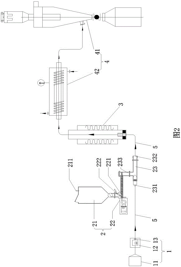
[0067] Example 3: Rapid pyrolysis in high temperature inert atmosphere
[0068] Open the feed bin 21, add the powder material to be pyrolyzed into the feed bin 21, and close the discharge port 221 of the screw feeder. Immediately begin to evacuate feed bin 21. Gradually open the discharge port 221 of the screw feeder to fill the entire silo 21 with inert gas; then recirculate the process of closing the discharge port 221-vacuumize-introduce the inert gas, repeat 2~3 times, and complete the silo 21 Change the atmosphere inside.
[0069] At the same time, start to pass inert gas into the whole system except the silo 21 through the gas control unit 1 for purging for 5-30 minutes, and the time can be extended appropriately according to the required cleanliness, so that the whole system can be transformed into an inert gas environment. After the purging is completed, the air flow control module 12 is adjusted to reduce the air flow and maintain a continuous small air flow.
[00...
PUM
 Abstract
Description
Claims
Application Information
 - R&D Engineer
- R&D Manager
- IP Professional
- Industry Leading Data Capabilities
- Powerful AI technology
- Patent DNA Extraction
Browse by: Latest US Patents, China's latest patents, Technical Efficacy Thesaurus, Application Domain, Technology Topic, Popular Technical Reports.
© 2024 PatSnap. All rights reserved.Legal|Privacy policy|Modern Slavery Act Transparency Statement|Sitemap|About US| Contact US: help@patsnap.com


