Tray positioning push part of lower box mechanism

A technology of tray trays and lower boxes, which is applied in the direction of conveyor objects, conveyors, transportation and packaging, etc., can solve the problem that the lower box mechanism cannot be used for common transmission mechanisms, and achieves the effect of simple structure

Active Publication Date: 2018-03-13
CHENGDU SOONTRUE MECHANICAL EQUIP CO LTD
View PDF13 Cites 0 Cited by
  • Summary
  • Abstract
  • Description
  • Claims
  • Application Information

AI Technical Summary

Problems solved by technology

[0005] In order to overcome the problem that the existing box-down mechanism cannot be used in common with the existing transmission mechanism in practical applications, a box positioning and pushing part of the box-down mechanism that can assist in solving the above problems is proposed

Method used


Image

  • Tray positioning push part of lower box mechanism
  • Tray positioning push part of lower box mechanism
  • Tray positioning push part of lower box mechanism

Examples


Embodiment 1

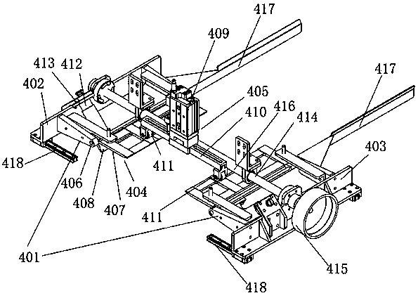
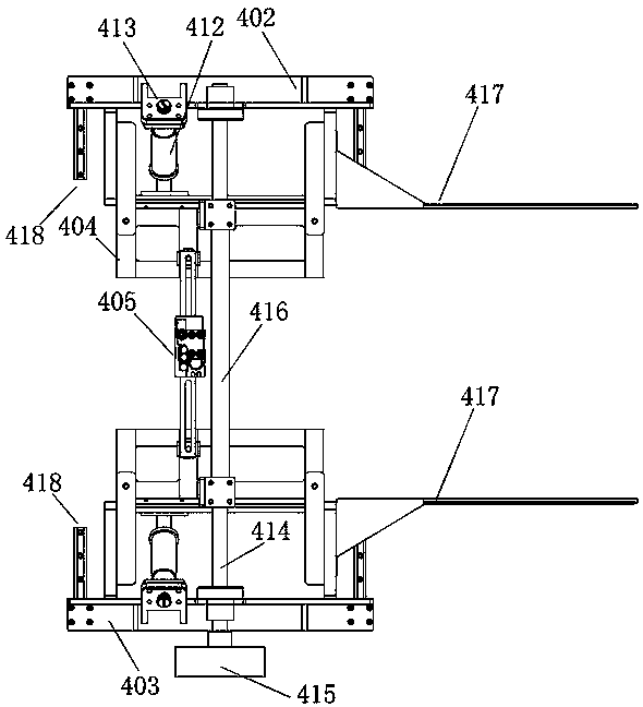
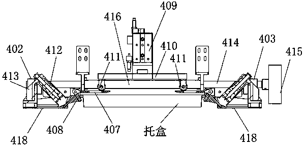
[0034]The bracket positioning push part of the lower box mechanism includes a positioning mounting bracket 401, and the positioning mounting bracket 401 includes a left bracket 402 and a right bracket 403, and the inner sides of the left bracket 402 and the right bracket 403 are each provided with a bracket for supporting the bracket. Cartridge card slot 404, the two tray card slots 404 are symmetrically arranged, and the openings of the two symmetrically arranged tray card slots 404 are parallel to each other, and a pressing device for pushing down the tray box is arranged above the tray card slot 404 405 , the tray slot 404 is connected to the positioning installation frame 401 through the slot rotation shaft 406 . The left support 402 and the right support 403 are respectively provided with a tray draw-in slot 404, and the tray tray is positioned between the two tray draw-in slots 404, and the tray tray is supported by the two tray draw-in slots 404, and now the pressing dev...

Embodiment 2

[0036] The bracket positioning push part of the lower box mechanism includes a positioning mounting bracket 401, and the positioning mounting bracket 401 includes a left bracket 402 and a right bracket 403, and the inner sides of the left bracket 402 and the right bracket 403 are each provided with a bracket for supporting the bracket. Cartridge card slot 404, the two tray card slots 404 are symmetrically arranged, and the openings of the two symmetrically arranged tray card slots 404 are parallel to each other, and a pressing device for pushing down the tray box is arranged above the tray card slot 404 405 , the tray slot 404 is connected to the positioning installation frame 401 through the slot rotation shaft 406 .

[0037] The tray draw-in slot 404 comprises a draw-in slot horizontal plate 407 and a draw-in slot slant plate 408 fixedly connected. The slant plate 408 and the card slot are connected to the installation frame through the card slot rotating shaft 406 at the sa...


PUM


Abstract

The invention relates to the fields of mechanical processing and box packing, in particular to a supporting box positioning and pushing component of a box lowering mechanism. The supporting box positioning and pushing component comprises a positioning mounting rack. The positioning mounting rack comprises a left support and a right support. The inner side of the left support and the inner side of the right support are each provided with a supporting box clamping groove used for supporting a supporting box. The two supporting box clamping grooves are formed symmetrically, and openings of the two supporting box clamping grooves formed symmetrically are parallel to each other. A pressing device used for pushing the supporting box downwards is arranged above the supporting box clamping grooves. The supporting box clamping grooves are connected with the positioning mounting rack through clamping groove rotary shafts. The supporting box pushed horizontally can be positioned in the positioning mounting rack and then are pushed downwards to fall, and thus the supporting box can fall onto a conveying belt of any specification. In this way, the structure of the supporting box positioning and pushing component can be matched with existing conveying belts of various specifications, and the trouble that when a lifting adsorption component is used for adsorbing a supporting box downwards, the existing conveying belts need to be modified is avoided.

Description

technical field [0001] The invention relates to the field of mechanical processing and packing, in particular to a box positioning and pushing part of a box lowering mechanism. Background technique [0002] In the existing field of mechanical processing and boxing, when the products to be boxed are processed, it is usually necessary to perform boxing operations, but the existing boxing is basically to put the food directly into the tray by hand, and stack The trays together often need to be placed manually so that the products can automatically fall into the trays. [0003] In view of the above situation, the applicant applied for the existing patent for improving the cartoning process. For example, the patent application number is CN201520254060.6, the application date is 2015.04.24, and the practical name is "the unloading mechanism of the food cartoning machine". The new type patent, its technical proposal is: the utility model relates to the field of food processing mac...

Claims


Application Information

Patent Timeline
Patent Type & Authority Patents(China)
IPC IPC(8): B65G47/04
CPCB65G47/04B65G2201/025
Inventor 薛博勋彭涛
Owner CHENGDU SOONTRUE MECHANICAL EQUIP CO LTD
Why Eureka
Try Eureka