Large-load underwater releasing and recovering system

A recovery system and large-load technology, applied in the direction of ships, etc., can solve the problems of increasing the test cost and manpower and material resources, damage and release of the releaser, pollution of the test water area, etc., to achieve the effect of easy operation, large release load, and simple system construction.

Inactive Publication Date: 2016-10-12
NO 719 RES INST CHINA SHIPBUILDING IND
View PDF9 Cites 9 Cited by
  • Summary
  • Abstract
  • Description
  • Claims
  • Application Information

AI Technical Summary

Problems solved by technology

This method of flotation test determines that a certain weight of external counterweight will be discarded each time the model is floated, resulting in the need to purchase and carry a considerable amount of external counterweight for each test, which greatly increases the test cost and manpower and material resources; at the same time, a large number of discarded External counterweights (such as: iron blocks, stones, etc.) with the bottom of the water will also cause pollution to the test water area
Therefore, this method is only suitable for floating model tests with small scale and few working conditions. It is not recommended for floating model tests with many working conditions and large scale.
[0004] In addition, the original underwater release system mostly uses a single releaser to release the counterweight. This method has the following problems: First, if a single releaser fails, the power is insufficient, etc., the trip test will fail. Re-hoist the model and counterweight, replace the releaser, or repair and recharge, etc.; second, the rated load of a single releaser is limited when released. If the rated load is exceeded, the releaser may be damaged or the release may fail.

Method used


Image

  • Large-load underwater releasing and recovering system
  • Large-load underwater releasing and recovering system

Examples


Embodiment Construction

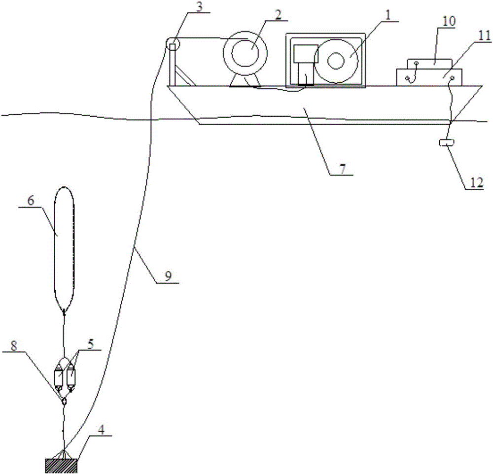
[0014] Refer to the attached drawings, the large-load underwater release and recovery system, which is used to release the experimental model 6 and recover the external counterweight 4. It includes: a test platform 7, a generator 1 and a hoist 2 mounted on the test platform 7 , Guide pulley and bracket 3, signal generator 10, power amplifier 11, underwater release unit 5, and transmitting transducer 12;

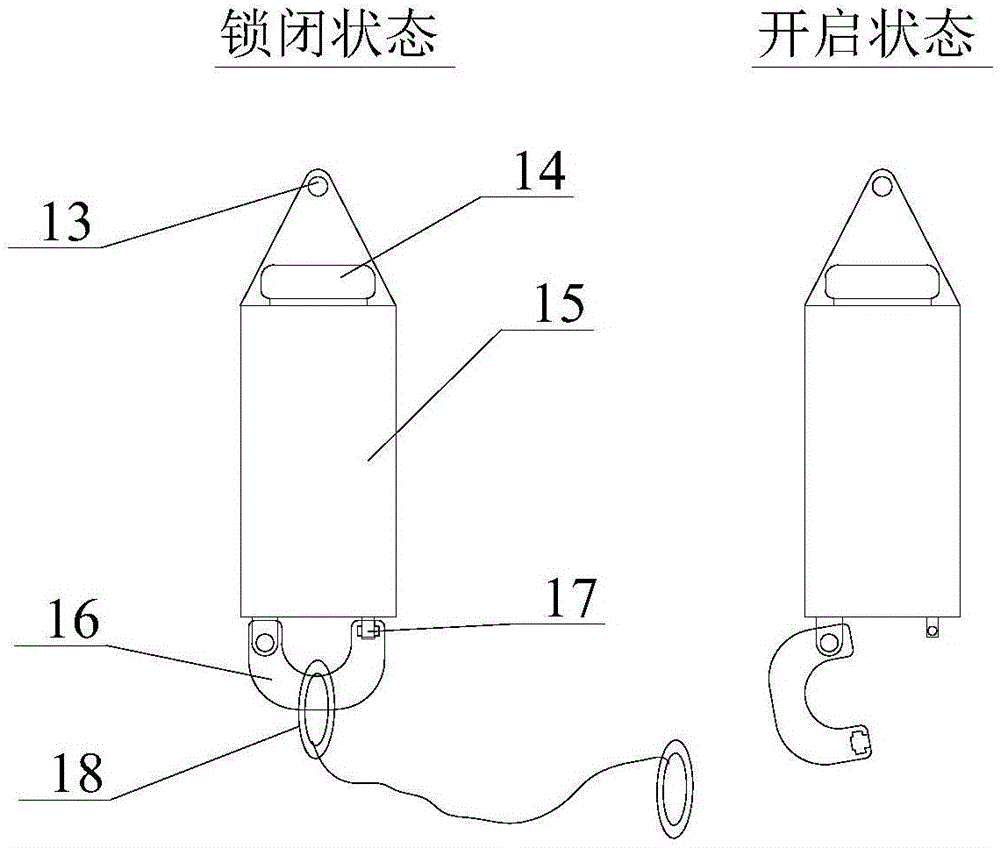
[0015] There are two underwater release units 5, including: a pressure-resistant protective housing 15 with a fixed mounting hole 13 at the top, a release hook 16 and a limit rod 17 connected to the bottom, and installed in the pressure-resistant protective housing 15 The receiving hydrophone 14; the front part of the release hook 16 is provided with a card slot, which cooperates with the limit rod 17, and the limit rod 17 rotates under the control of the internal motor to realize the separation or combination with the release hook 16; The release hook 16 of the two underwater r...


PUM


Abstract

The invention belongs to the technical field of underwater testing, in particular to an underwater release and recovery system. The large-load underwater release and recovery system is used to release the experimental model and recover the external counterweight. The technical solution is: the generator supplies power to the winch through cables; the steel wire rope of the winch is connected to the external counterweight through guide pulleys and brackets ; The top fixed installation holes of the two underwater release units are connected together by cables and then connected to the test model, the release ring at the bottom of the underwater release unit is connected by a cable with a large ring, and the large ring and the external counterweight pass through The cables are connected; the output end of the signal generator is connected with the input end of the power amplifier, and the output end of the power amplifier is connected with the transmitting transducer. The system of the present invention is relatively simple to build and easy to operate, and most of the components have shelf products, which can significantly improve the test efficiency, save the test cost and reduce the work intensity of the test personnel.

Description

Technical field [0001] The invention belongs to the technical field of underwater testing, and particularly relates to an underwater release and recovery system. Background technique [0002] When the underwater vehicle is operating at high speed, hydrodynamic noise is an important source of radiated noise. In order to verify the hydrodynamic noise characteristics of the underwater vehicle by using test methods, it is usually carried out through two test methods of shallow water towing and deep water floating. In the test, the deep water buoyancy test connects the test model and the ballast weight through an underwater release system. Under a certain water depth, the release system works to separate the test model and the ballast weight. Under the net buoyancy of the model, the model Accelerate the ascent to achieve the hydrodynamic noise test at the higher speed of the model. [0003] At present, the supporting facilities required for deep-water floating tests generally include s...

Claims


Application Information

Patent Timeline
Patent Type & Authority Applications(China)
IPC IPC(8): B63B21/16B63B21/20
CPCB63B21/16B63B21/20
Inventor 郑国垠孙国仓黎雪刚徐俊华如南
Owner NO 719 RES INST CHINA SHIPBUILDING IND
Why Eureka
Try Eureka