Mechanical arm capable of automatically being closed

An automatic closing and manipulator technology, applied in the field of manipulators, can solve the problems that the safety of employees who shuttle between machines cannot be guaranteed, the production cost cannot be reduced, and the parts to be processed fall off. The effect of preventing parts from falling off

Inactive Publication Date: 2016-10-12
SUZHOU GAOTONG MACHINERY TECH CO LTD
View PDF11 Cites 0 Cited by
  • Summary
  • Abstract
  • Description
  • Claims
  • Application Information

AI Technical Summary

Problems solved by technology

Among the existing factories, there are still some production factories that still use the manual feeding method of production and manufacturing. On the one hand, the production cost cannot be reduced, and on the other hand, it is convenient to shuttle between machines. The safety of employees cannot be guaranteed.
At the same time, the manipulator is prone to the problem of the parts to be processed falling off during the process of grabbing the product, and the parts falling on the processing device are easy to cause the machine to malfunction.

Method used


Image

  • Mechanical arm capable of automatically being closed
  • Mechanical arm capable of automatically being closed
  • Mechanical arm capable of automatically being closed

Examples


Embodiment 1

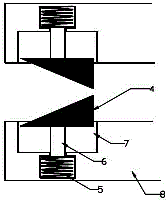
[0021] Such as figure 1 As shown, an automatically closed manipulator includes a fixed rod, a mechanical claw 2, a one-way door structure 9; the mechanical claw 2 is U-shaped; the one-way door structure 9 includes a slider 4, a spring 5, and a spring block 6;

[0022] Such as figure 1 As shown, the mechanical claw 2 includes an upper half, a bend 3 and a lower half; the upper half is provided with a circular hole, the upper half is sleeved on the fixed rod 1 through the circular hole, and the upper half is fixedly connected to the fixed rod 1;

[0023] The top of the bend 3 is fixedly connected to the upper half, and the bottom of the bend is fixedly connected to the lower half;

[0024] Such as figure 2 As shown, the lower half is provided with five equally spaced long holes to divide the lower half into six grid blocks 8. Each long hole is provided with two one-way door structures 9, the leftmost and the most The width of the two grid blocks on the right is less than or equal to t...

Embodiment 2

[0029] A mechanical hand that can be closed automatically, comprising a fixed rod, a mechanical claw 2, a one-way door structure 9; the mechanical claw 2 is U-shaped; the one-way door structure 9 includes a slider 4, a spring 5 and a spring block 6;

[0030] The mechanical claw 2 includes an upper half, a bending 3 and a lower half; the upper half is provided with a circular hole, the upper half is sleeved on the fixed rod 1 through the circular hole, and the upper half is fixedly connected to the fixed rod 1, and bent 3 The top part is fixedly connected to the upper body, and the bent bottom part is fixedly connected to the lower body;

[0031] Such as Figure 4 As shown, the lower half is provided with five equally spaced long holes to divide the lower half into six grid blocks 8. The size of the six grid blocks 8 is equal, and each grid block 8 is provided with a single Toward the door structure 9, such as Figure 5 As shown, a groove 7 is opened on the end of the grid block 8 ...


PUM


Abstract

The invention discloses a mechanical arm capable of automatically being closed, and belongs to the technical field of mechanical arms. The mechanical arm comprises a fixing rod, a mechanical gripper and one-way door structures; the one-way door structures comprise sliding blocks, springs and elastic blocks; an upper half body is fixedly connected with the fixing rod, the top of a bending part is fixedly connected with the upper half body, and the bottom of the bending part is fixedly connected with a lower half body; a plurality of long holes are formed in the lower half body at equal intervals, and the lower half body is divided by the long holes into a plurality of grid blocks, the one-way door structures are arranged on the grid blocks, grooves are formed in one ends, far away from the bending part, of the grid blocks, the springs and the elastic blocks are arranged in the grooves, the spring is arranged at the tops of the elastic blocks, the tops of the elastic blocks are closely clamped in the grooves, and the bottoms of the elastic blocks are fixedly connected with the sliding blocks. The mechanical arm is simple in structure, the production manufacturing procedure is small during large-scale outputting, and cost is greatly reduced; human labor can be replaced, the production cost is reduced, it can be avoided that parts fall off in the process that the parts are grabbed, and it is guaranteed that the parts can stably enter the following procedure.

Description

Technical field [0001] The invention relates to a manipulator that can be automatically closed, belonging to the technical field of manipulators. Background technique [0002] At present, when processing the parts to be processed, it is necessary to go through a lot of processes. From the previous process to the next process, a transmission device is required for transmission. How to accurately transfer the parts or materials to be processed to the corresponding Work position is an important factor to measure work efficiency and production quality. Among the existing factories, there are still some production factories that still use manual feeding manufacturing methods. On the one hand, production costs cannot be reduced, and on the other hand, the safety of employees who shuttle between machines is not guaranteed. At the same time, the manipulator is prone to the problem of the parts to be processed falling off during the process of grasping the products, and the parts falling...

Claims


Application Information

Patent Timeline
Patent Type & Authority Applications(China)
IPC IPC(8): B25J15/08
CPCB25J15/08
Inventor 汪金旺
Owner SUZHOU GAOTONG MACHINERY TECH CO LTD
Why Eureka
Try Eureka