Eureka AIR delivers breakthrough ideas for toughest innovation challenges, trusted by R&D personnel around the world.

Power factor correction circuit, multiplier and voltage feedforward circuit

A voltage feedforward, multiplier technology, applied in the direction of high-efficiency power electronic conversion, output power conversion devices, electrical components, etc., can solve the problems of affecting the multiplier output, long time setting, slow response, etc., to save energy System cost, increased hold-up time, effect of filtering out transient fluctuations

Active Publication Date: 2018-08-21
COSEMITECH SHANGHAI CO LTD
View PDF4 Cites 0 Cited by
  • Summary
  • Abstract
  • Description
  • Claims
  • Application Information

AI Technical Summary

Problems solved by technology

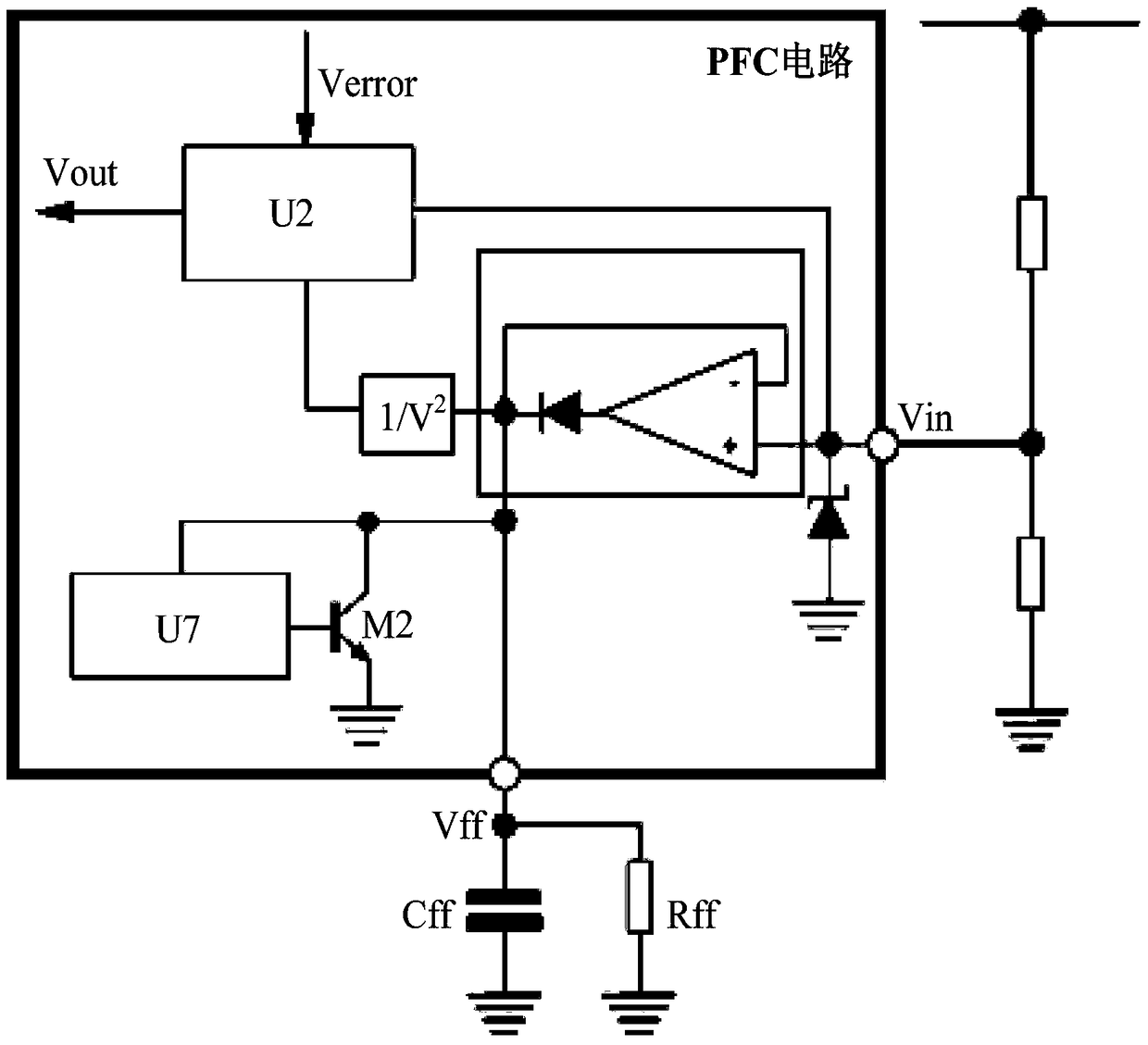
figure 2 The disadvantage of the medium voltage feedforward circuit is that an additional PIN pin is required to connect the external resistor Rff and the external capacitor Cff
In addition, there is a compromise between the value of the external capacitor Cff and the external resistor Rff. For example, if the value of the external capacitor Cff is too small, there will be a large ripple on the external capacitor Cff, which will affect the output of the multiplier and increase distortion. , reducing the effect of power factor correction; if the value of the external capacitor Cff is too large, the response will slow down, and it will take longer to set the correct voltage feed-forward value, which will lead to a large overvoltage or undervoltage in the output voltage. to press

Method used


Image

  • Power factor correction circuit, multiplier and voltage feedforward circuit
  • Power factor correction circuit, multiplier and voltage feedforward circuit
  • Power factor correction circuit, multiplier and voltage feedforward circuit

Examples


specific Embodiment approach

[0140] Example embodiments will now be described more fully with reference to the accompanying drawings. Example embodiments may, however, be embodied in many forms and should not be construed as limited to the embodiments set forth herein; rather, these embodiments are provided so that this disclosure will be thorough and complete, and will fully convey the concept of example embodiments to those skilled in the art. Furthermore, the described technical features or circuit structures may be combined in any suitable manner in one or more embodiments. In the following description, numerous specific details are provided in order to give a thorough understanding of the embodiments of the present disclosure. However, one skilled in the art will appreciate that the techniques of the present disclosure may be practiced without one or more of these specific details.

[0141] Certain words are used to refer to specific components in the specification and claims, and those skilled in ...


PUM


Abstract

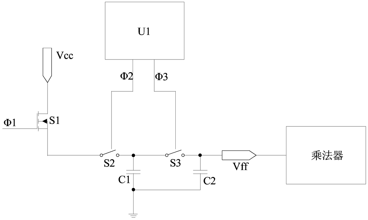
The present disclosure provides a voltage feedforward circuit, a multiplier using the voltage feedforward circuit, and a power factor correction circuit using the multiplier. The voltage feedforward circuit is applied to a multiplier for maintaining and outputting a peak voltage of an input voltage, which includes: a first switching element, a logic control unit, a second switching element, a third switching element and a second capacitor. The disclosure is beneficial to improving the stability of the power factor correction circuit and the response speed to the input voltage, and improving the linearity of the multiplier and the accuracy of the output current of the multiplier.

Description

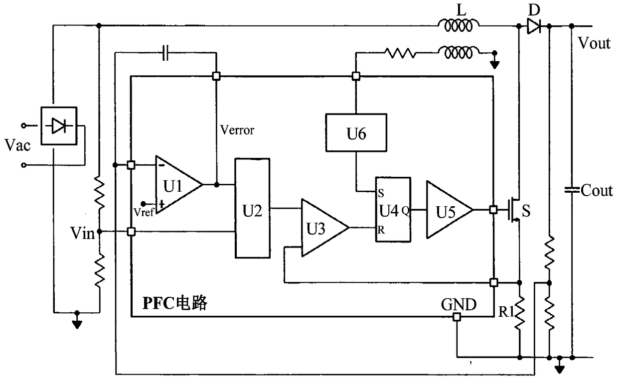
technical field [0001] The present disclosure relates to the technical field of power management, and in particular to a voltage feedforward circuit, a multiplier using the voltage feedforward circuit, and a power factor correction circuit using the multiplier. Background technique [0002] In order to utilize grid power more efficiently, power factor correction technology has been widely used in switching power supply technology. In the prior art, it is common practice to insert a first-stage power factor correction (Power Factor Correction, PFC) circuit between the diode rectifier bridge of the circuit and the load, so that the current drawn from the AC power supply is also a sine wave signal, and its phase follows power supply voltage varies. After adding the power factor correction circuit, the power factor value can be close to 1. [0003] An implementation of a PFC circuit such as figure 1 Shown in, which is applied to a boost converter (BoostConverter). The conver...

Claims


Application Information

Patent Timeline
Patent Type & Authority Patents(China)
IPC IPC(8): H02M1/42
CPCH03D7/1433H03D7/1458H02M1/4225Y02B70/10Y02P80/10H02M1/4208H03D7/1441
Inventor 游剑尹小平
Owner COSEMITECH SHANGHAI CO LTD
Why Eureka
Eureka Blog
Learn More