
Defective point detection system and method for vertical cavity surface emitting laser array

A technology of vertical cavity surface emission and laser array, which is applied in testing optical performance and other directions, and can solve problems such as low efficiency, large quantity, and visual fatigue

Inactive Publication Date: 2016-10-05
NINGBO SUNNY OPOTECH CO LTD
View PDF5 Cites 2 Cited by
  • Summary
  • Abstract
  • Description
  • Claims
  • Application Information

AI Technical Summary

Problems solved by technology

And when there are only individual bad pixels, it may be difficult to observe only by human eyes, which leads to a decrease in the accuracy of the detection process
[0008] Secondly, when the human eyes directly face the light source for a long time and focus on one place for a long time, it is easy to cause visual fatigue
In this unavoidable situation, the detection accuracy rate of the same worker will also drop, which may cause the array with dead pixels that could have been detected to be undetected due to visual fatigue
[0009] Third, each VCSEL array used in the projection module must go through the process of array dead point detection, that is to say, dead point detection must be a long-term and huge amount of work
Therefore, in such a fixed and repetitive work process, one of the obvious problems in the manual detection method is that the efficiency is low
[0010] Fourth, the human eye directly faces the light source for a long time, which is easy to damage the human eye. This is not a good working environment for the staff for this kind of process that needs to be batched and carried out for a long time

Method used


Image

  • Defective point detection system and method for vertical cavity surface emitting laser array
  • Defective point detection system and method for vertical cavity surface emitting laser array
  • Defective point detection system and method for vertical cavity surface emitting laser array

Examples


Embodiment Construction

[0056] The following description serves to disclose the present invention to enable those skilled in the art to carry out the present invention. The preferred embodiments described below are only examples, and those skilled in the art can devise other obvious variations. The basic principles of the present invention defined in the following description can be applied to other embodiments, variations, improvements, equivalents and other technical solutions without departing from the spirit and scope of the present invention.

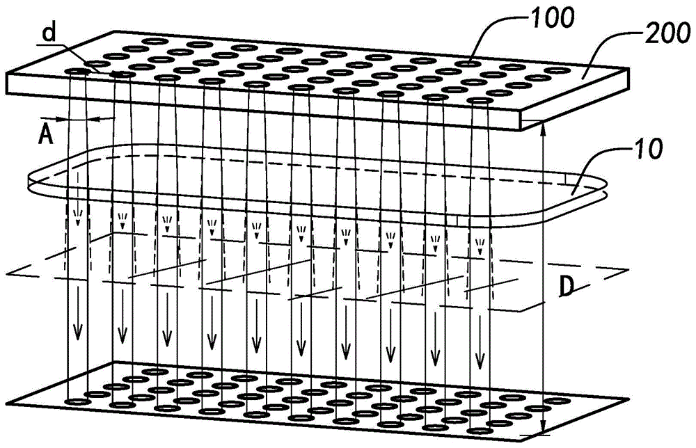
[0057] refer to figure 1 is a schematic diagram of a VCSEL array. In order to replace the method of directly observing and judging with human eyes in the detection process in the prior art, it is necessary to start from understanding the basic structure and imaging method of VCSEL, and explore how to make VCSEL imaging not be imaged on the human retina, but indirectly imaged on the imaging device. This can preliminarily replace the direct observation of...


PUM


Abstract

The invention relates to a defective point detection system for a vertical cavity surface emitting laser (VCSEL) array. The system comprises a lens device, an image collection device, and an analysis and determination device. The lens device is used for increasing an imaging distance of a VCSEL array. The image collection device is used for collecting an image of the VCSEL array. And the analysis and determination device is used for analyzing and determining information of the VCSEL array image collected by the image collection device and determining whether a defective point exists in the VCSEL array. In addition, the invention also provides a defective point detection method for a VCSEL array. The method comprises: (A), a lens device is provided and is arranged in front of a light-emitting unit of a VCSEL array, so that an imaging distance of the VCSEL array increases; (B), an image collection device is provided and an image of the VCSEL array through the lens device is collected; and (C), an analysis and determination device is provided, and thus information of the VCSEL array image collected by the image collection device is analyzed and whether a defective point exists in the VCSEL array is determined.

Description

technical field [0001] The present invention relates to a dead point detection system and method of a vertical cavity surface emitting laser array, and further relates to a dead point detection system and method of a vertical cavity surface emitting laser array applied to a projection module. Background technique [0002] VCSEL (Vertical Cavity Surface Emitting Laser) is a new type of semiconductor laser, which has the advantages of single longitudinal mode operation, circular cross-section emitting light, easy to form a two-dimensional array, and suitable for on-line wafer-level testing. It is widely used. In various fields, for example, in the application of projection modules. [0003] During the production process of the VCSEL array, it is inevitable to cause dead pixels, which will cause partial areas of the module to have no light, and affect the function of the projection module, which needs to be selected before use. Among them, the dead point refers to the pixel po...

Claims


Application Information

Patent Timeline
IPC IPC(8): G01M11/02
Inventor 张扣文鲁丁李强余梦璐
Owner NINGBO SUNNY OPOTECH CO LTD
Learn More