
Core-pulling self-locking mechanism of injection mold

An injection mold and self-locking technology, applied in the field of core-pulling self-locking mechanism, can solve problems such as increasing costs, prolonging production cycle, and occupying mold space

Active Publication Date: 2016-10-05
NINGBO XINGLI AUTOMOBILE MOLD
View PDF3 Cites 6 Cited by
  • Summary
  • Abstract
  • Description
  • Claims
  • Application Information

AI Technical Summary

Problems solved by technology

[0008] Option 1: Adding an additional oil cylinder not only increases the cost, but also has strict requirements on the space position of the mold, and increases the processing cost. In addition, it also has a certain impact on the strength of the mold, and there are too many actions in the production to prolong the production cycle;
[0009] Option 2 uses a self-locking cylinder, although it is not affected by other aspects, but the price of the self-locking cylinder is 5 to 10 times the price of the general cylinder, or even more, which increases the cost;
[0010] Option 3 is to install an oil cylinder with a sufficiently large bore if the space permits. On the one hand, it occupies a large amount of space in the mold, and the problem to be solved cannot be completely solved. On the other hand, the price of the oil cylinder with a larger bore is higher. And the piston sealing requirements of the oil cylinder will be very high;
[0011] Plan 4 adds a self-locking valve at the oil inlet of the existing oil cylinder, which requires high sealing performance of the piston of the oil cylinder. At the same time, the service life of the self-locking valve is not long. Further, the price of the oil cylinder with high sealing requirements is very high

Method used


Image

  • Core-pulling self-locking mechanism of injection mold
  • Core-pulling self-locking mechanism of injection mold
  • Core-pulling self-locking mechanism of injection mold

Examples


Embodiment Construction

[0027] The present invention will be described in further detail below in conjunction with the accompanying drawings and specific embodiments.

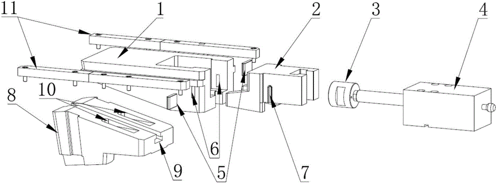
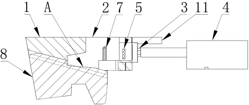
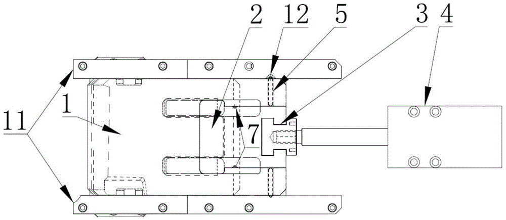
[0028] A core-pulling self-locking mechanism for an injection mold, comprising a wedge block 1, a small wedge block 2, a core-pulling block 8 and a drive unit, the drive unit drives the small wedge block 2 to perform linear reciprocating motion, and the wedge block 1 is provided with a through hole 6, and a positioning block 5 is arranged in the through hole 6, and the positioning block 5 can slide along the inner wall of the through hole 6, and the small wedge block 2 is provided with a first groove 7. The first groove 7 is used to limit the positioning block 5 in the through hole 6. A bead 11 is provided on both sides of the wedging block 1, and a second concave is provided on the bead 11. Groove 12, the second groove 12 is used to limit the positioning block 5 in the through hole 6, a core-pulling block 8 is provided under the wedg...


PUM


Abstract

The invention relates to a core-pulling self-locking mechanism of an injection mold. The core-pulling self-locking mechanism comprises a wedging block, a small wedge block, a core-pulling block and a driving unit, and is characterized in that the driving unit drives the small wedge block to do linear reciprocating motion; a through hole is formed in the wedging block; a positioning block is arranged in the through hole and capable of sliding along the inner wall of the through hole; a first groove is formed in the small wedge block; a pressing strip is arranged on each of the two sides of the wedging block; second grooves are formed in the pressing strips; the core-pulling block is arranged below the wedging block; a third groove is formed in the core-pulling block; and the wedging block is embedded into the third groove. According to the core-pulling self-locking mechanism provided by the invention, the occupied space and cost of the mechanism are not increased; the small wedge block and the core-pulling block are arranged to form a certain included angle, so requirements for core pulling and self-locking can be met; and the requirements of the mechanism on an oil cylinder and machining precision are not high, the structure of the mechanism is simple, reliable, compact and durable, and the movement time is not wasted in a production process.

Description

technical field [0001] The invention relates to an injection mold, in particular to a core-pulling self-locking mechanism of an injection mold. Background technique [0002] When using an oil cylinder to lock a large-area product surface for core-pulling, the injection pressure acting on the core-pulling surface is often greater than the locking pressure of the oil cylinder, which will cause the core-pulling retreat and produce steps or burrs. In order to solve this problem, the existing technology mainly uses The following scheme: [0003] Solution 1. Add an oil cylinder on the side to drive the wedge block to lock the core puller; [0004] Option 2. Self-locking cylinder for oil cylinder; [0005] Option 3. Install an oil cylinder with a sufficiently large bore diameter if the space permits; [0006] Solution 4. Add a self-locking valve at the oil inlet of the existing oil cylinder. [0007] The above four schemes have the following disadvantages respectively: [0008...

Claims


Application Information

Patent Timeline
IPC IPC(8): B29C45/33B29C45/40B29C45/64
Inventor 邬荣武裴东良李国发章垚统任远耀张学军潘海东陈云
Owner NINGBO XINGLI AUTOMOBILE MOLD
Learn More