
Secondary side control circuit, secondary side control method, and fly-back converter adopting the same

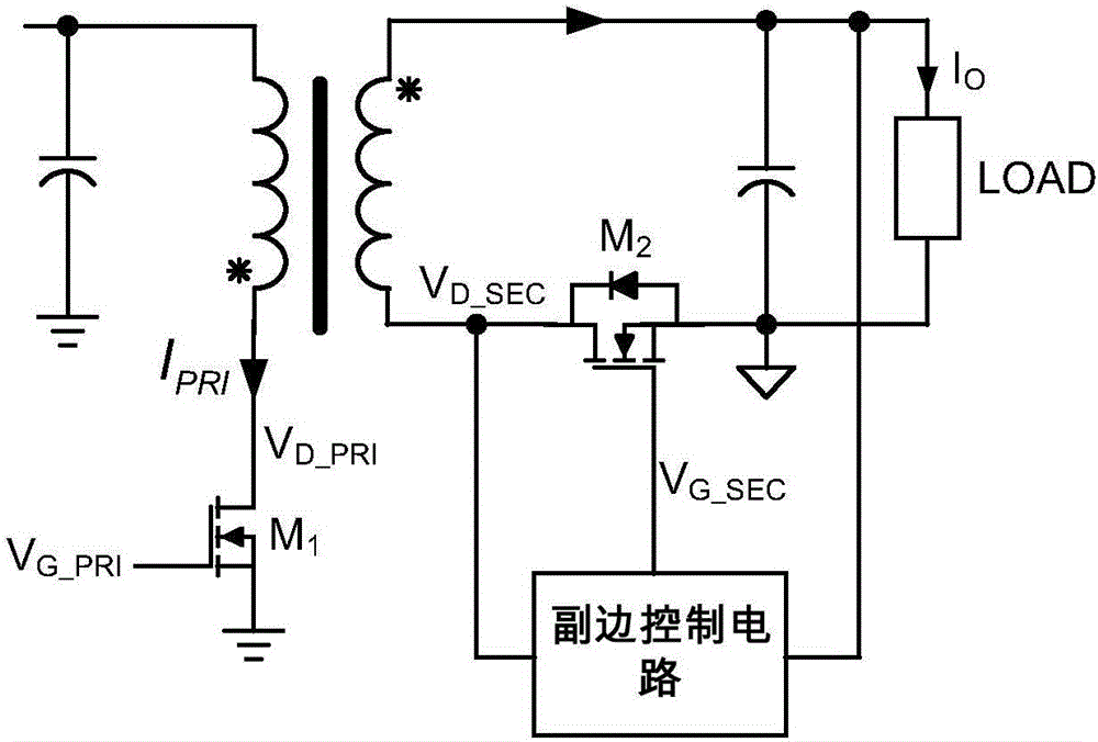
A flyback converter and control circuit technology, applied in the direction of regulating electrical variables, control/regulating systems, high-efficiency power electronic conversion, etc., can solve the problem of misleading conduction of the secondary side rectifier switch M2, and achieve the effect of avoiding misleading conduction.

Active Publication Date: 2016-09-28
西安矽力杰半导体技术有限公司
View PDF6 Cites 30 Cited by
  • Summary
  • Abstract
  • Description
  • Claims
  • Application Information

AI Technical Summary

Problems solved by technology

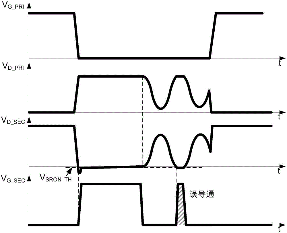
[0004] However, when the flyback converter operates in discontinuous conduction mode (DCM), such as image 3 As shown, in each switching cycle, when the energy in the transformer is released to the secondary side, since the main power switch of the primary side is not turned on, due to the existence of circuit parasitic parameters, the voltage of the primary winding will start to resonate. The resonance of the voltage will be transmitted to the secondary side through the transformer, making the voltage V D_SEC resonate
If the resonance amplitude is large, the voltage V D_SEC During resonance it is possible to drop below the turn-on threshold V SRON_TH , which will cause the secondary side rectifier switch M2 to be falsely turned on

Method used


Image

  • Secondary side control circuit, secondary side control method, and fly-back converter adopting the same
  • Secondary side control circuit, secondary side control method, and fly-back converter adopting the same
  • Secondary side control circuit, secondary side control method, and fly-back converter adopting the same

Examples


Embodiment Construction

[0079] The present invention is described below based on examples, but the present invention is not limited to these examples. In the following detailed description of the invention, some specific details are set forth in detail. The present invention can be fully understood by those skilled in the art without the description of these detailed parts. In order not to obscure the essence of the present invention, well-known methods, procedures, procedures, components and circuits have not been described in detail.

[0080] Additionally, those of ordinary skill in the art will appreciate that the drawings provided herein are for illustrative purposes and are not necessarily drawn to scale.

[0081] Meanwhile, it should be understood that in the following description, "circuit" refers to a conductive loop formed by at least one element or sub-circuit through electrical connection or electromagnetic connection. When an element or circuit is said to be "connected to" another eleme...


PUM


Abstract

The invention discloses a secondary side control circuit, a secondary side control method, and a fly-back converter adopting the same. By using a characteristic of a secondary side winding changing slowly during a primary side resonance period, a slope parameter representing a change of a secondary side detection voltage along a preset direction is compared with a slope parameter threshold, and only when the slope of the secondary side detection voltage is large (when the change is fast, or the changing amplitude in unit time is large), the secondary side detection voltage is allowed to be lower than a conducting threshold, and a secondary side rectification switch is triggered to be switched on. The reason of the voltage drop of the secondary side winding is switching off of a primary side main power switch or parasitic parameters is determined, and the error switching-on of the secondary side rectification switch is prevented.

Description

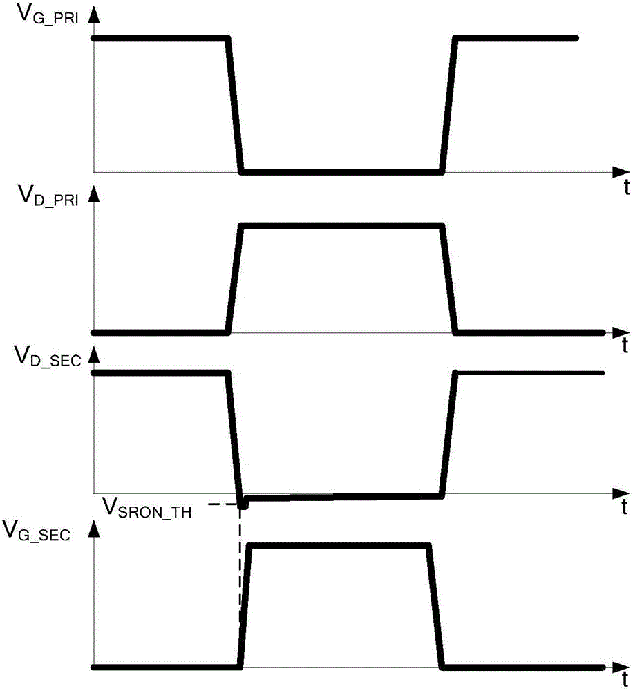
technical field [0001] The invention relates to power electronics technology, in particular to a secondary side control circuit, a control method and a flyback converter using the same. Background technique [0002] The flyback converter (Fly-back Convertor) has the characteristics of high conversion efficiency and low loss. The existing primary-side control flyback converter realizes the adjustment of the output voltage or current by controlling the main power switch arranged on the primary side of the transformer. At the same time, in the prior art, on the secondary side of the flyback converter, using the secondary side rectification switch to replace the original diode for synchronous rectification can significantly reduce the rectification loss, thereby improving the conversion efficiency of the flyback power supply. A flyback converter using synchronous rectification technology such as figure 1 shown. [0003] The existing control strategy of the secondary rectifier...

Claims


Application Information

Patent Timeline
IPC IPC(8): H02M3/335
CPCH02M3/33576H02M1/0029H02M3/33592Y02B70/10H02M1/08H02M3/33507H02M3/285H02M7/1557H02M1/0003
Inventor 杨笑宇胡志亮白永江
Owner 西安矽力杰半导体技术有限公司
Learn More