Counterweight combined water tanks for pressure test of foundation tubular piles and pressure test method

A technology for combining water tanks and water tanks, which is applied in basic structure tests, basic structure engineering, construction, etc., and can solve problems such as accidents, damage to bottom water tanks, and load-bearing frame dumping

Active Publication Date: 2016-09-28
侯伯贵
View PDF5 Cites 1 Cited by
  • Summary
  • Abstract
  • Description
  • Claims
  • Application Information

AI Technical Summary

Problems solved by technology

[0003] Now the water tank is filled with water as the heavy object used for the pressure test foundation pipe pile. The disadvantage is that if the water tank is small in size, if the load-bearing frame on the foundation pile is tilted, the water in the water tank pressed on the load-bearing frame It will lean towards the lower side, and a large number of water tanks on the load-bearing frame will all tilt in one direction, and the entire load-bearing frame will topple over, causing an accident.
If the volume of the water tank is large, the bottom water tank cannot withstand the upward force of the hydraulic pump for pressure test placed on the foundation pipe pile, and the bottom water tank will be damaged.

Method used


Image

  • Counterweight combined water tanks for pressure test of foundation tubular piles and pressure test method
  • Counterweight combined water tanks for pressure test of foundation tubular piles and pressure test method
  • Counterweight combined water tanks for pressure test of foundation tubular piles and pressure test method

Examples


Embodiment 1

[0085] Embodiment 1, the two-layer combined water tank used in the foundation pipe pile for water tank pressure test

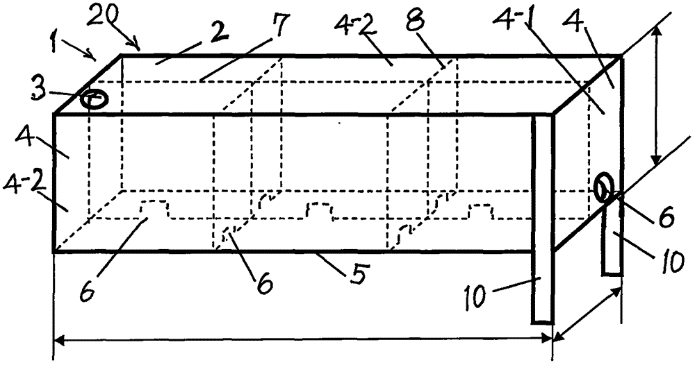
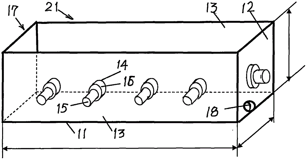
[0086] Such as figure 1 , 2 , 3, the used two-layer combined water tank of water tank pressure test foundation pipe pile, comprises bottom water tank 20 and upper water tank 21, and upper water tank 21 overlaps and places above bottom water tank 20;

[0087] [1], the structure of the bottom water tank 20: including a rectangular steel box 1 fixedly connected on six sides, one or more water inlet holes 3 are provided on the top plate 2 of the rectangular steel box 1, and on the side plate 4 of the rectangular steel box 1 One or more water outlet holes 6 are provided near the bottom plate 5; the side plate 4 of the rectangular steel box 1 includes two small side plates 4-1 on the opposite side, and two large side plates 4-1 on the opposite side. 2;

[0088] In the rectangular steel box 1, one or more long partitions 7 are fixedly connected between the two sma...

Embodiment 2

[0103] Embodiment 2, the three-layer combined water tank used in the foundation pipe pile for water tank pressure test

[0104] Such as figure 1 , 2 , 3, the three-layer combined water tank used for the foundation pipe pile of the water tank pressure test,

[0105] [1], same as embodiment 1;

[0106] [2], same as embodiment 1;

[0107] [3], same as embodiment 1;

[0108] [4], same as embodiment 1;

[0109] [5], same as embodiment 1;

[0110] [6], the upper strata water tank 21 external dimensions of small size are:

[0111] Box bottom plate 11, its external dimensions are: length 12.3 meters, width 2.7 meters;

[0112] The end face side panel 12 has the dimensions: 2.7 meters wide and 2.8 meters high;

[0113] Front side panel 13, its external dimensions are: length 12.3 meters, height 2.8 meters;

[0114] [7], the upper strata water tank 21 external dimensions of big size are:

[0115] Box bottom plate 11, its external dimensions are: length 12.6 meters, width 2.9 m...

Embodiment 3

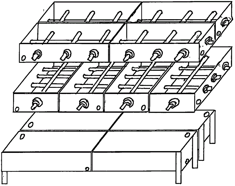
[0118] Embodiment 3, four bottom water tanks 20 " device " font arrangement type combined water tanks, the method of pressure test detection method for foundation pipe piles is as follows figure 1 , 2 , 3, 4, with four bottom water tanks 20 of embodiment 1 " device " font arrangement type combined water tank, to foundation pipe pile pressure test detection method, four bottom water tanks 20 of " device " font arrangement are pressed on foundation foundation On the pipe pile, the specific steps are as follows:

[0119] [1], Build pressure test and load-bearing combination device: place test pressure gauge 32 on the foundation pipe pile 31 to be tested, place concentrated pressure thick steel plate 33 on test pressure gauge 32, place component force on concentrated pressure thick steel plate 33 Bearing frame 34;

[0120] [2], Stacking the elevated strip piles for stably placing the water tank: use soil or building material solids on the ground on the opposite sides of the meas...


PUM


Abstract

The invention discloses counterweight combined water tanks for the pressure test of foundation tubular piles and a pressure test method, and belongs to the technical field of pile foundation detection of a building. The combined water tanks include the four bottom-layer water tanks which are arranged on the foundation tubular piles in a Chinese character 'qi' shape and the four upper-layer water tanks which are overlapped on the four bottom-layer water tanks in a Chinese character 'chuan' shape. The pressure test method includes the steps that (1) a pressure test and load bearing combined device is built; (2) a supporting strip-shaped stack for stable arrangement of the water tanks is formed; (3) the four bottom-layer water tanks arranged in the Chinese character 'qi' shape are arranged; (4) water is injected into the four bottom-layer water tanks to increase the weight; (5) the four upper-layer water tanks arranged in the Chinese character 'chuan' shape are arranged on the four bottom-layer water tanks; and (6) a pressure test instrument is started to detect the descending height of the foundation tubular piles under test. The counterweight combined water tanks for the pressure test of the foundation tubular piles and the pressure test method have the advantages that the conveying quantity of counterweight objects is reduced by eight times, the conveying efficiency is improved, the conveying expenses are reduced, the bottom-layer water tanks are prevented from inclining or toppling over in the direction away from the foundation tubular piles, and the purpose that the water tanks can be filled with water to serve as a counterweight and provide pressure for the foundation tubular piles is achieved.

Description

technical field [0001] The invention belongs to the technical field of pile foundation detection of buildings, in particular to a counterweight device and a pressure test detection method for the pressure test of foundation pipe piles. Background technique [0002] The current pressure test method for foundation pipe piles is to pile up the weight required for pressure testing with concrete weights on the foundation pipe piles, often hundreds of tons or thousands of tons are stacked on a foundation pipe pile Ton weight is used to test the pressure of the foundation pipe piles to determine the pressure resistance of the foundation pipe piles. This method needs hundreds of tons of thousands of tons of cement blocks as heavy objects, and these hundreds of tons of thousands of tons of cement blocks are transported from a construction site to other construction sites as heavy objects to consume a large amount of manpower and expense. [0003] Now the water tank is filled with wa...

Claims


Application Information

Patent Timeline
IPC IPC(8): E02D33/00
CPCE02D33/00
Inventor 侯伯贵
Owner 侯伯贵
Why Eureka
Try Eureka