
Air-oxygen mixing structure for breathing machine and breathing machine

An oxygen mixing and ventilator technology, applied in the field of ventilators, can solve problems such as inaccurate detection, insufficient gas mixing, unstable pressure at the flow detection port, etc., achieve sufficient mixing, prevent turbulence from affecting flow detection, and have a simple structure Effect

Active Publication Date: 2016-09-28
HUNAN MICOME ZHONGJIN MEDICAL SCI & TECH DEV CO LTD
View PDF14 Cites 7 Cited by
  • Summary
  • Abstract
  • Description
  • Claims
  • Application Information

AI Technical Summary

Problems solved by technology

However, the flow detection port on the rear side of the pressure drop perforated wall of this structure in the prior art is located in the mixing chamber, and the air flow entering from the air inlet and the oxygen flow entering from the oxygen inlet are likely to form a turbulent flow at the flow detection port, resulting in The pressure at the back-end flow detection port is very unstable, which makes the detection inaccurate
Moreover, the gas of this structure also has the problem of insufficient gas mixing
[0004] In order to solve the problems of inaccurate detection and uneven mixing of air and oxygen, the following air and oxygen mixing mechanisms or devices for ventilators are disclosed in the prior art:

Method used


Image

  • Air-oxygen mixing structure for breathing machine and breathing machine
  • Air-oxygen mixing structure for breathing machine and breathing machine
  • Air-oxygen mixing structure for breathing machine and breathing machine

Examples


Embodiment 1

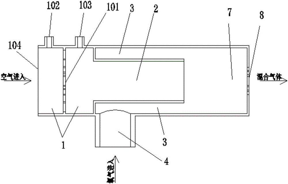
[0074] Such as figure 1 As shown, this embodiment provides an air-oxygen mixing structure for a ventilator, including:

[0075] Air flow detection chamber 1, air diversion chamber 2, oxygen diversion chamber 3, mixing chamber 7;

[0076] The inlet end of the air flow detection chamber 1 is an air inlet 104, and the outlet end of the air flow detection chamber 1 communicates with the inlet end of the air diversion chamber 2; the air flow detection chamber 1 is provided with a pressure drop perforated wall 101, and the pressure drop perforated wall The front and rear sides of 101 are respectively provided with flow detection port 1 102 and flow detection port 2 103;

[0077] The air guiding cavity 2 is a cylindrical cavity, the oxygen guiding cavity 3 is an annular cavity arranged on the periphery of the air guiding cavity 2, and the outer wall of the oxygen guiding cavity 3 is provided with an oxygen inlet 4; the air guiding cavity 2 and the outlet end of the oxygen guide ch...

Embodiment 2

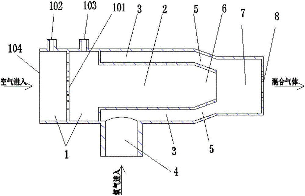
[0088] Such as figure 2 As shown, this embodiment provides an air-oxygen mixing structure for a ventilator, including:

[0089] Air flow detection chamber 1, air diversion chamber 2, oxygen diversion chamber 3, air mixing diversion chamber 6, oxygen mixing diversion chamber 5, mixing chamber 7;

[0090] The inlet end of the air flow detection chamber 1 is an air inlet 104, and the outlet end of the air flow detection chamber 1 communicates with the inlet end of the air diversion chamber 2; the air flow detection chamber 1 is provided with a pressure drop perforated wall 101, and the pressure drop perforated wall The front and rear sides of 101 are respectively provided with flow detection port 1 102 and flow detection port 2 103;

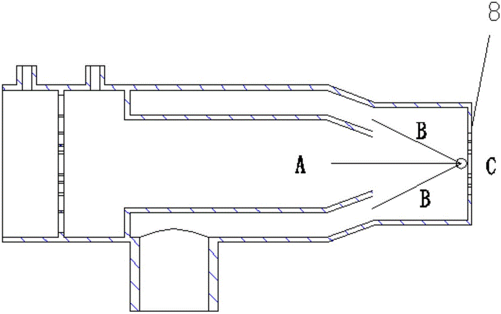
[0091] The air guiding cavity 2 is a cylindrical cavity, the oxygen guiding cavity 3 is an annular cavity arranged on the outer periphery of the air guiding cavity 2, and the outer wall of the oxygen guiding cavity 3 is provided with an oxygen inl...

Embodiment 3

[0102] The difference between this embodiment and embodiment 2 is:

[0103] The cross-sectional area ratio of the oxygen guiding cavity 3 and the air guiding cavity 2 is 1:2;

[0104]The oxygen mixing diversion cavity 5 is inclined inwardly at an angle of 15°;

[0105] The total area of ​​circular holes on the pressure drop perforated wall accounts for 50% of the area of ​​the pressure drop perforated wall;

[0106] The total area of ​​the circular holes on the mixed perforated wall 8 accounts for 60% of the area of ​​the mixed perforated wall.


PUM


Abstract

The invention provides an air-oxygen mixing structure for a breathing machine and the breathing machine. The air-oxygen mixing structure comprises an air flow detecting cavity, an oxygen guide cavity, an air guide cavity and a mixing cavity. The inlet end of the air flow detecting cavity is an air inlet, and the outlet end of the air flow detecting cavity is communicated with the inlet end of the air guide cavity. A pressure-drop holed wall is arranged in the air flow detecting cavity, and a flow detecting port I and a flow detecting port II are respectively arranged on the front side and the rear side of the pressure-drop holed wall. The air guide cavity is a circular-ring-shaped cavity arranged on the periphery of the air guide cavity, and an oxygen inlet is formed in the outer wall of the oxygen guide cavity. The inlet end of an oxygen mixing guide cavity and the inlet end of an air mixing guide cavity are respectively communicated with the oxygen guide cavity and the air guide cavity, and the outlet ends of the two cavities are both communicated to the mixing cavity. The outlet end of the mixing cavity is provided with a mixing holed wall. The air-oxygen mixing structure is used for the breathing machine and has the advantages of being simple in structure, capable of preventing turbulent flows from influencing flow detection and making gases be mixed fully.

Description

technical field [0001] The invention relates to an air-oxygen mixing structure for a ventilator and the ventilator, belonging to the technical field of ventilators. Background technique [0002] In modern clinical medicine, the ventilator, as an effective means of artificially replacing the spontaneous ventilation function, has been widely used in respiratory failure caused by various reasons, anesthesia respiratory management during major surgery, respiratory support treatment and emergency resuscitation. It occupies a very important position in the field of modern medicine. Ventilator is a vital medical equipment that can prevent and treat respiratory failure, reduce complications, save and prolong the life of patients. [0003] During the use of the ventilator, the patient must be mechanically ventilated. For the patient being treated, the control of the ventilation volume and the adjustment of the oxygen concentration are very important, especially for infant patients a...

Claims


Application Information

Patent Timeline
IPC IPC(8): A61M16/00A61M16/12A61M16/20
CPCA61M16/0003A61M16/12A61M16/203A61M2016/003A61M2016/102A61M2016/1025A61M2205/3334A61M2205/42
Inventor 戴征丁锦刘炜徐勤鹏万昭军
Owner HUNAN MICOME ZHONGJIN MEDICAL SCI & TECH DEV CO LTD
Learn More