Self-sealing sliding contact conductive device

A conductive device, self-enclosed technology, applied in the direction of circuits, current collectors, electrical components, etc., can solve problems such as no solution, high cost, difficult construction, etc., to prevent personal electric shock and line leakage accidents, low cost, easy to manufacture and install Easy and fast effect

Inactive Publication Date: 2016-09-21
北京大赢电气有限公司
View PDF5 Cites 0 Cited by
  • Summary
  • Abstract
  • Description
  • Claims
  • Application Information

AI Technical Summary

Problems solved by technology

It will inevitably cause problems such as complex structure, difficult construction, and high cost.
However, there is no suitable and ideal solution for narrow spaces, curved running routes and within the reach of the human body at any time.

Method used


Image

  • Self-sealing sliding contact conductive device
  • Self-sealing sliding contact conductive device
  • Self-sealing sliding contact conductive device

Examples


Embodiment Construction

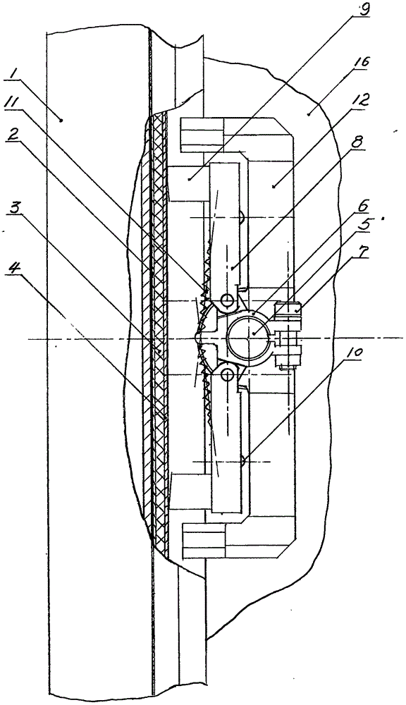
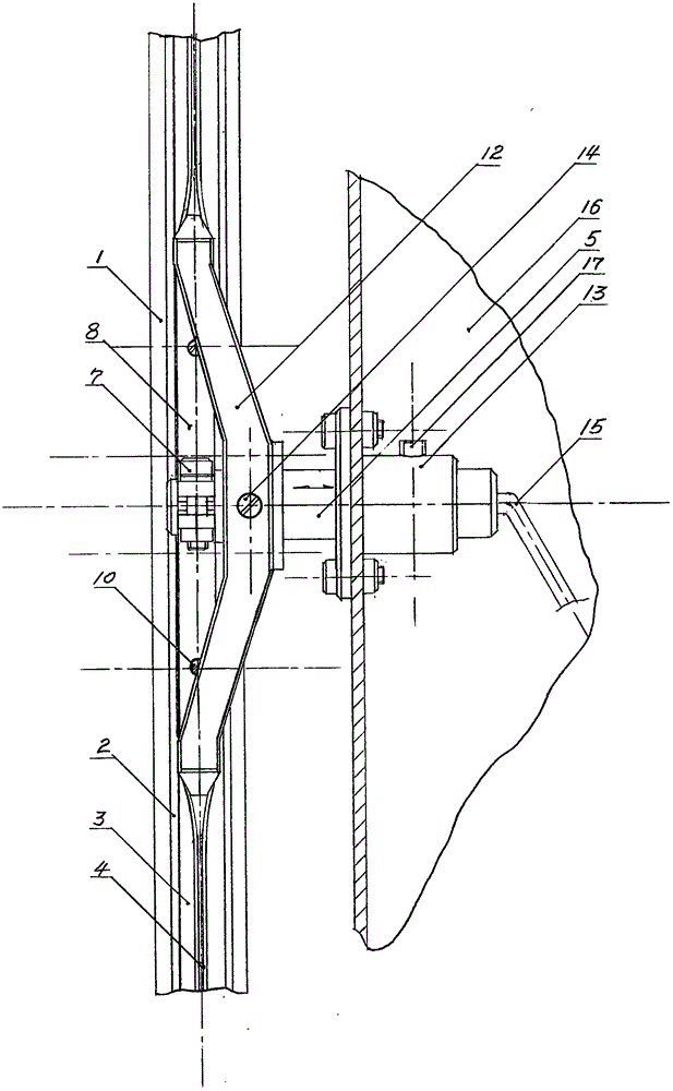
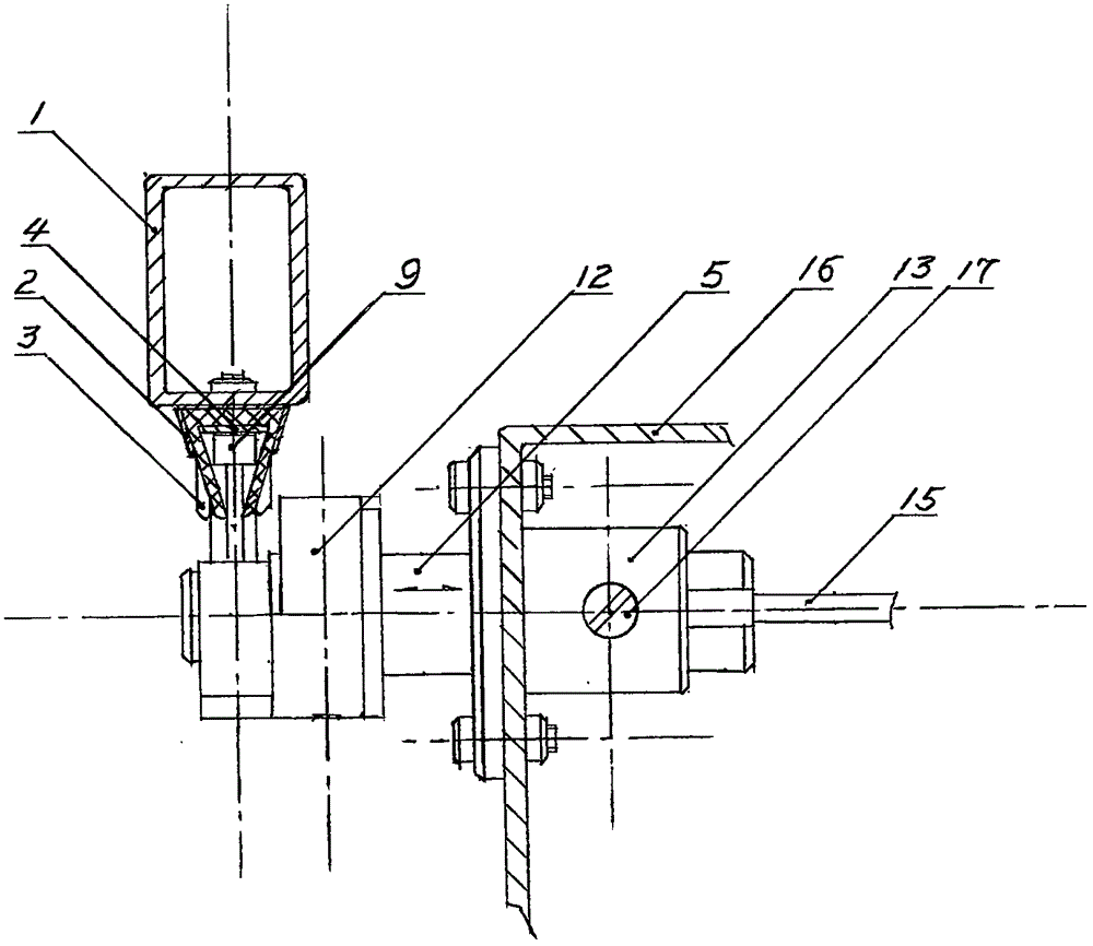
[0011] In the figure, the conductive red copper strip (4) is inlaid in the inner bottom of the triangular rubber insulating base strip (3) with an opening at the front corner, and is held by the conductive strip shell (2) to form a conductive strip assembly of the entire length, which is installed on the conductive strip shell (2). on the bracket tube (1) and connect it to the power supply. Fix the copper sliding contact center frame (6) on the outer end shaft head of the sliding contact insulation center shaft (5), and fasten it together with the outer end of the wire (15) with the fastening screw (7) Together. The two wings of the copper sliding contact center frame (6) are respectively fitted with a conductive voltage arm (8), and the ends of the two conductive voltage arms (8) are each fitted with a graphite brush (9). And fasten firmly by electric brush fastening screw bar (10). Two conduction voltage arms are tensioned by a compression arm extension spring (11) respect...


PUM


Abstract

The invention provides a self-sealing sliding contact conductive device. A conductive copper belt is inlayed into the inner bottom of a triangular rubber insulating base band with a front corner opening. The housing of the conductive belt snaps the rubber insulating base band, thereby forming a conductive belt assembly. The conductive copper belt is connected with a power supply. A copper slide contact central bracket is snapped on the outer end of a slide contact insulating central shaft. Two ends of the copper slide contact central bracket are respectively provided with a conductive pressure arm. The ends of the two conductive pressure arms are provided with graphite brushes which are equipped in a snapping manner. Furthermore two extension springs draw the two conductive pressure arms to tight. The inside slide contact central shaft of the copper slide contact central shaft is provided with a double-head nylon cutting blade. Prism cutter heads at two ends of the double-head nylon cutting blade are inserted into openings of the rubber insulating base band, thereby partially opening the rubber insulating base band so that appropriate spaces exist for realizing elastic pressing of the graphite brushes on the conductive copper belt. The slide contact insulating central shaft is mounted in a supporting guide sleeve in a movable fit manner. The supporting guide sleeve is mounted at an appropriate position of an electric power transmission host machine housing. A lead which is connected with the copper slide contact central bracket is connected with an electric power consumption power system. Accordingly, the self-sealing sliding contact conductive device which can perform reciprocation motion is formed.

Description

Technical field [0001] The invention relates to a sliding contact conductive device which can be self-closed during the whole operation to prevent personal electric shock and circuit leakage. Background technique [0002] At present, most of the power supply methods for long-distance power carrying equipment adopt high-altitude erection, underground concealed sliding contact conductive methods or accompanying cables to follow the power supply to prevent personal electric shock and line leakage. It will inevitably cause problems such as complex structure, difficult construction, and high cost. And in narrow space, in the running route of curve and in the scope that human body can touch at any time, still do not have appropriate ideal solution. Contents of the invention [0003] In order to reasonably solve the problem of the power supply mode of the long-distance power carrying equipment mentioned above. The invention provides a self-enclosed sliding contact conductive de...

Claims


Application Information

Patent Timeline
Patent Type & Authority Applications(China)
IPC IPC(8): H01R41/00
CPCH01R41/00
Inventor 单玉治
Owner 北京大赢电气有限公司
Why Eureka
Try Eureka