Side-in type backlight module and liquid crystal display device

An edge-type backlight and module technology, which is applied in the field of edge-type backlight modules and liquid crystal display devices, can solve the problems of reducing production efficiency, weakening bright spots, uneven brightness and darkness of spots, etc., so as to improve the overall reliability, Improve the visual effect and solve the problem of bright spots

Inactive Publication Date: 2016-09-21
HISENSE VISUAL TECH CO LTD
View PDF8 Cites 0 Cited by
  • Summary
  • Abstract
  • Description
  • Claims
  • Application Information

AI Technical Summary

Problems solved by technology

[0004] In order to solve this bright spot problem, in the early stage, solutions such as optimizing the dot design of the light guide plate and attaching black PET were adopted, but optimizing the dot design of the light guide plate can only weaken the bright spot phenomenon, and attaching black PET will reduce production efficiency and easily introduce spots The problem of uneven brightness and darkness leads to the inability to fundamentally solve the problem of bright spot on the positioning column, which affects the luminous effect and reliability of the side-type backlight module, which in turn affects the visual effect of the liquid crystal display device and reduces the user experience

Method used


Image

  • Side-in type backlight module and liquid crystal display device
  • Side-in type backlight module and liquid crystal display device
  • Side-in type backlight module and liquid crystal display device

Examples


Embodiment Construction

[0023] In order to make the purpose, technical solutions and advantages of the embodiments of the present invention clearer, the technical solutions in the embodiments of the present invention will be clearly and completely described below in conjunction with the drawings in the embodiments of the present invention. Obviously, the described embodiments It is a part of embodiments of the present invention, but not all embodiments. Based on the embodiments of the present invention, all other embodiments obtained by persons of ordinary skill in the art without making creative efforts belong to the protection scope of the present invention.

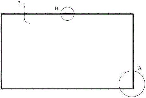
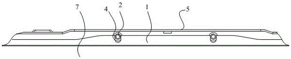
[0024] In order to solve the problem of bright spots on the positioning column 2, this embodiment relates to a side-entry backlight module, see Figure 4 to Figure 6 , comprising a backplane 5, a light guide plate 1, a light source 6 and a heat dissipation plate 9, the light guide plate 1 and the heat dissipation plate 9 are both arranged on ...


PUM


Abstract

The invention relates to a side-in type backlight module which comprises a backboard, a light guide board, a light source and a heat radiation board. The light guide board and the heat radiation board are both arranged on the backboard. The light source is arranged on the heat radiation plate and at one side of the backboard. The backboard is provided with locating columns for locating the light guide board. Protruding parts protruding towards the outer side are arranged on the two sides, adjacent to the light source, of the light guide plate. The side faces, away from the light source, of the protruding parts are inclined faces inclining towards the light source. The side face, close to the light source, of each protruding part is a plane supported on the locating column on the same side. An inclination angle of 10-45 degrees is formed between the side face, away from the light source, of each protruding part and the plane where the plane perpendicular to the light source is located at the end, close to the light source, of the side face away from the light source, of each protruding part. According to the side-in type backlight module, the problem about bright spots of the locating columns can be solved, and the overall reliability of the side-in type backlight module can be improved.

Description

technical field [0001] The invention relates to the field of liquid crystal display, and more particularly relates to a side-entry backlight module and a liquid crystal display device. Background technique [0002] The edge-type products in the display equipment (for example, edge-type backlight module) are important display components, and their function is to supply sufficient brightness and evenly distributed light source, so that the liquid crystal display device can display images normally. Backlight modules are divided into side-type and direct-type according to different light incident methods. The side-type backlight module usually consists of a backplane, a light source, a light guide plate, and a liquid crystal panel. The light source is arranged on the backplane through a heat sink, and the light emitted by the light source enters the liquid crystal panel through the light guide plate. [0003] In order to provide sufficient and uniform brightness and avoid the m...

Claims


Application Information

Patent Timeline
Patent Type & Authority Applications(China)
IPC IPC(8): G02F1/13357
CPCG02F1/133615G02F1/133606G02F1/133611
Inventor 王慧石磊
Owner HISENSE VISUAL TECH CO LTD
Why Eureka
Try Eureka