
Low-cost LED bulb lamp easy to dissipate heat

A low-cost LED bulb lamp, applied in lighting and heating equipment, components of lighting devices, semiconductor devices of light-emitting elements, etc., can solve the problems of inconvenient packaging and production, low production efficiency, complex structure, etc., and achieve heat dissipation Excellent effect, simple structure, large luminous area

Pending Publication Date: 2016-09-21
ZHEJIANG INTELED OPTOELECTRONICS TECH
View PDF0 Cites 1 Cited by
  • Summary
  • Abstract
  • Description
  • Claims
  • Application Information

AI Technical Summary

Problems solved by technology

[0003] The invention provides an LED bulb lamp which is easy to dissipate heat and low cost, and is easy to dissipate heat and has a low-cost LED bulb lamp in which heat-conducting gas is filled in a sealed bulb shell and a driving power source which shares a substrate with the LED light source is integrated and packaged; Inconvenience, low productivity and high cost

Method used


Image

  • Low-cost LED bulb lamp easy to dissipate heat
  • Low-cost LED bulb lamp easy to dissipate heat
  • Low-cost LED bulb lamp easy to dissipate heat

Examples


Embodiment 1

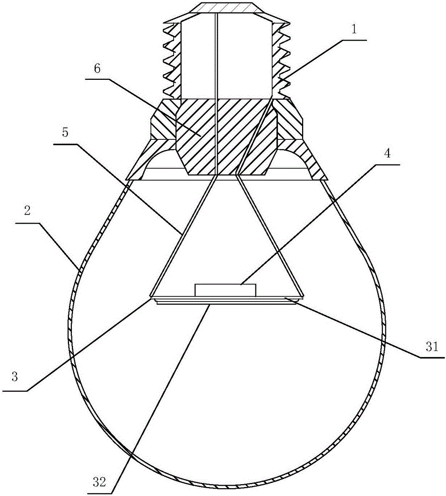
[0018] Example 1: see figure 1 , a low-cost LED bulb lamp that is easy to dissipate heat, includes a lamp cap 1 and a bulb case 2 connected thereto with a sealed storage space, the bulb case 2 is provided with an LED light source 3 positioned relative to the space formed therein, and the LED light source 3 It includes a substrate 31 and an LED light-emitting chip 32 arranged on one side of the substrate 31, and a drive power supply 4 integrated and packaged on the substrate 31 and arranged on the same substrate as the LED light-emitting chip 32. The bulb shell 2 is filled with an inert gas for heat conduction. The LED light source installed in the bulb shell can emit light after being powered on, and the bulb shell is made of transparent or translucent material, so that the light transmission performance is better. The LED light source needs DC power supply, and the driving power supply can convert the AC power supply into DC power supply. The driving power supply is integrate...

Embodiment 2

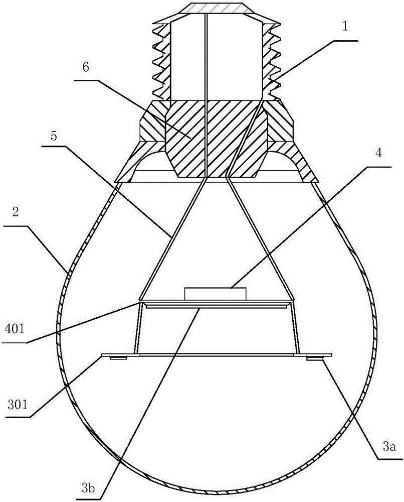
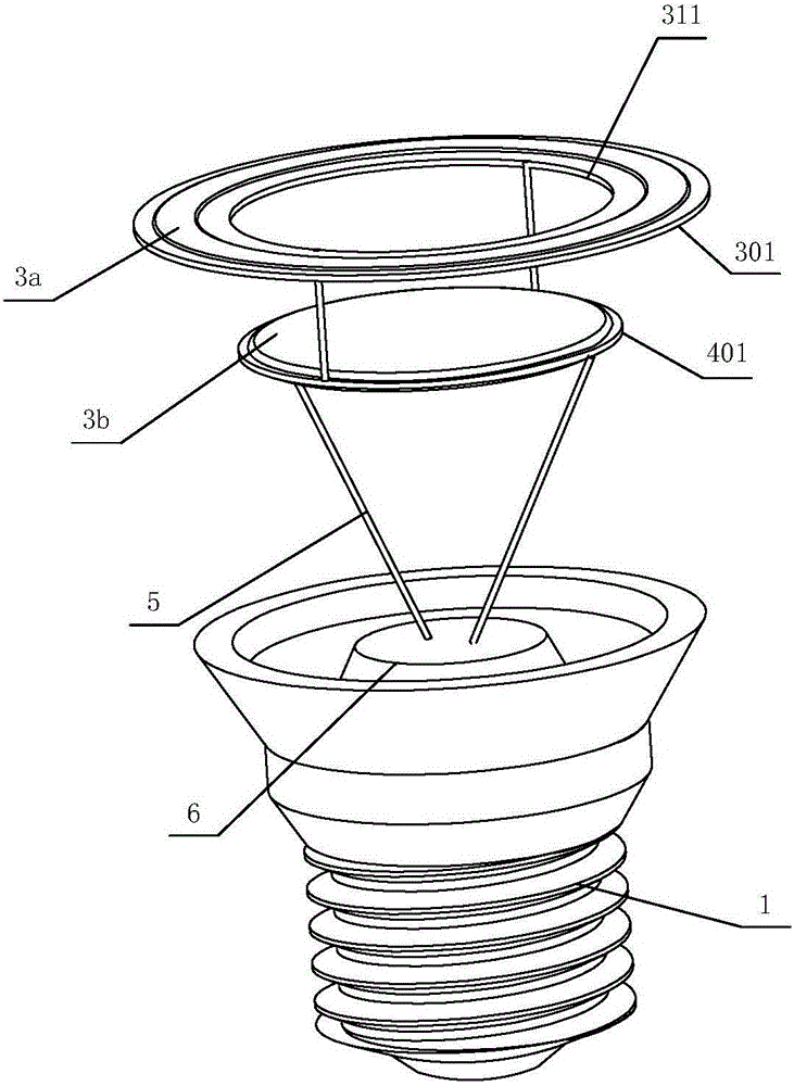
[0020] Example 2: see figure 2 , image 3 The LED light source includes a first light source 3a arranged coaxially with the lamp holder 1 and having a planar ring structure, and a second light source 3b arranged coaxially and parallel to the first light source 3a. The through hole 311 arranged coaxially connects the first light source 3a and the second light source 3b electrically, and the light-emitting surfaces of both are set facing away from the lamp cap 1 and facing downward. The LED light source includes a first light source that is coaxially arranged with the lamp head and is a planar ring structure, and a second light source that is coaxially and parallelly arranged with the first light source. The first light source and the second light source emit light together, and the two complement each other. It eliminates the shortcomings of the other party's lighting, has high luminous efficiency, and the formed lighting brightness is high, the light spot is good, and the to...


PUM


Abstract

The invention relates to a low-cost LED bulb lamp easy to dissipate heat. The LED bulb lamp comprises a lamp cap, and a bulb shell connected to the lamp cap and having a sealed accommodating space; and an LED light source forming the space positioning corresponding to the bulb shell is arranged in the bulb shell. The LED bulb lamp is characterized in that the LED light source includes a substrate, an LED light-emitting chip arranged on a single side of the substrate and a driving power supply integrated and packaged on the substrate and arranged on the substrate with the LED light-emitting chip; and inert gas for conducting heat is introduced into the bulb shell. The driving power supply and the LED light-emitting chip use the substrate to dissipate heat; then, the heat of heat conducting gas is transferred to the bulb shell; and the LED bulb lamp needs no additional heat dissipation structure, is simple in structure, greatly simplifies the production assembly process, greatly reduces the production cost, and is relatively good in heat dissipation effect.

Description

technical field [0001] The invention relates to a bulb lamp, in particular to an LED bulb lamp which is easy to dissipate heat and has low cost. Background technique [0002] LED light sources have the advantages of high efficiency and long life, and their life is much longer than that of ordinary incandescent lamps. As the country implements energy-saving and emission-reduction policies, the development of the energy-saving and environmentally-friendly LED industry is accelerating, LED lighting products are becoming more mature, and cost reduction has become a compulsory course for the entire industry. LED light sources need DC power supply, so generally LED lamps are equipped with a driving power source that can convert AC power into DC power. However, the driving power of the existing LED bulb lamp is set relatively independently. At the same time, the driving power supply and the LED light source will generate a lot of heat when they are working, so it needs an addition...

Claims


Application Information

Patent Timeline
Patent Type & Authority Applications(China)
IPC IPC(8): F21K9/232F21K9/278F21V23/00F21V29/70F21V19/00F21Y115/10
CPCF21V19/0015F21V23/002F21V23/003F21V29/70
Inventor 林成通李思昕胡乐新黄熙
Owner ZHEJIANG INTELED OPTOELECTRONICS TECH
Learn More