Anti-collision door
An anti-collision, door body technology, applied in door leaves, windows/doors, door/window accessories, etc., can solve problems such as hidden safety hazards, reduce door aesthetics, affect aesthetics, etc., and achieve the effect of avoiding collisions
- Summary
- Abstract
- Description
- Claims
- Application Information
AI Technical Summary
Problems solved by technology
Method used
Image
Examples
Embodiment 1
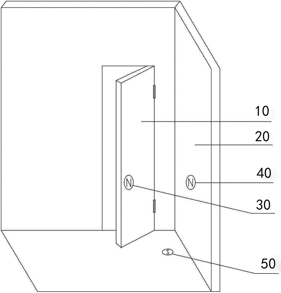
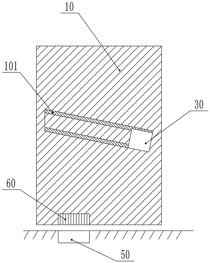
[0024] Such as figure 1 , figure 2 As shown, the anti-collision door includes the door body 10 hinged on the door frame, and also includes the first magnet 40 fixed on the wall body 20 and the second magnet 30 arranged on the door body 10, and the N level of the first magnet 40 Towards the outside of the door body 10 , the N-level of the second magnet 30 is outwards of the wall body 20 . Also be provided with the 3rd magnet 60 and the 4th magnet 50, the 4th magnet 50 is installed on the floor, the ground of the door body 10 is provided with a groove, the 3rd magnet 60 is installed in the groove, and the bottom surface of the door body 10 Flatter and more beautiful. Any one of the third magnet 60 and the fourth magnet 50 can be replaced by an iron block, and an anti-rust layer is coated on the iron block to increase the service life of the iron block. The door body 10 is made of wood, which is environmentally friendly and will not interfere with each magnet.
[0025] This ...
Embodiment 2
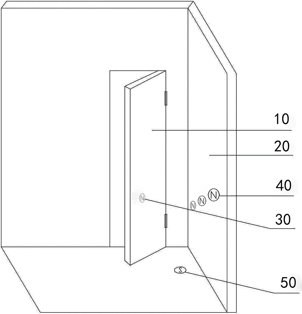
[0027] Such as image 3 As shown, the difference between this embodiment and Embodiment 1 is that: the door body 10 is provided with a first slide rail 101 for the second magnet 30 to slide, and the first slide rail 101 is inclined toward the lower right, and the inclination angle is About 20°. The number of the first magnets 40 is three, and the first magnets 40 are arranged correspondingly along the moving path of the second magnets 30 according to the magnitude of the magnetic force. And the magnetic force of the second magnet 30 away from the hinge point of the door body 10 and the door frame is greater than the magnetic force of the second magnet 30 close to the hinge point of the door body 10 and the door frame. When the second magnet 30 is farther away from the hinge point between the door body 10 and the door frame, it means that the second magnet 30 is subject to a greater centrifugal force and the door body 10 is faster. At this time, a greater force is needed to p...
Embodiment 3
[0029] Such as Figure 4 , Figure 5 As shown, the difference between this embodiment and Embodiment 2 is that a second slide rail 102 is also provided in the door body 10, the third magnet 60 can slide on the second slide rail 102, and the fourth magnet 50 is fixed on the ground. . The inclination angle of the second slide rail 102 is about 35°. The second magnet 30 and the third magnet 60 are connected together by a connecting rope 70, and the connecting rope 70 can be a nylon string to ensure strength and light weight. There is also a slit inside the door body 10 , the slit is mainly used for the movement of the connecting rope 70 , so as to ensure that the second magnet 30 and the third magnet 60 move synchronously.
[0030] When specifically opening and closing the door, if when a larger force is applied to the door body 10, the door body 10 bumps into the body of wall 20 at a higher speed, and the second magnet 30 moves toward the high end of the first slide rail 101,...
PUM
 Abstract
Description
Claims
Application Information
 - R&D Engineer
- R&D Manager
- IP Professional
- Industry Leading Data Capabilities
- Powerful AI technology
- Patent DNA Extraction
Browse by: Latest US Patents, China's latest patents, Technical Efficacy Thesaurus, Application Domain, Technology Topic, Popular Technical Reports.
© 2024 PatSnap. All rights reserved.Legal|Privacy policy|Modern Slavery Act Transparency Statement|Sitemap|About US| Contact US: help@patsnap.com


