
Motor Unit

A technology for motors and motor shafts, applied in electrical components, steering mechanisms, electromechanical devices, etc., can solve problems such as increasing heat generation, and achieve the effect of suppressing heat generation and size increase

Inactive Publication Date: 2016-09-07
JTEKT CORP
View PDF2 Cites 16 Cited by
  • Summary
  • Abstract
  • Description
  • Claims
  • Application Information

AI Technical Summary

Problems solved by technology

This increases the heat generation in the multiple semiconductor components of the module

Method used


Image

  • Motor Unit
  • Motor Unit
  • Motor Unit

Examples


Embodiment Construction

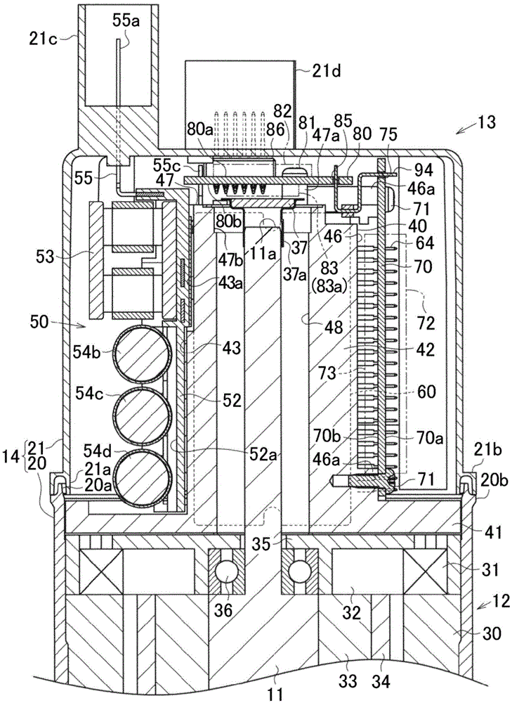
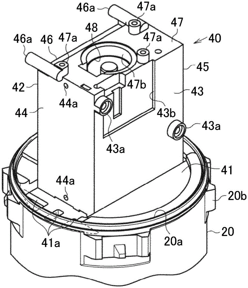
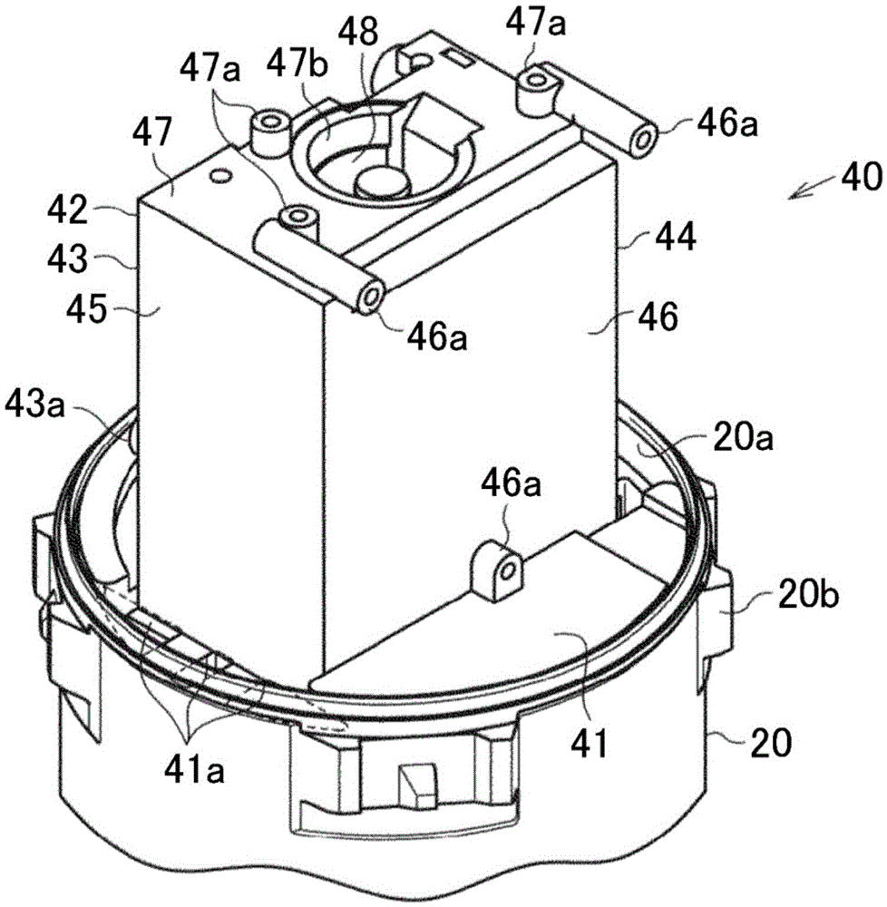
[0045] A motor unit according to an embodiment of the present invention will be described below. Such as figure 1 As shown in , the motor unit includes a motor 12 including a rotatable motor shaft 11 and the motor 12 operates when drive power is supplied to the motor 12, and a motor controller 13 that can perform the operation of driving the motor 12. control. The motor 12 and the motor controller 13 are accommodated in a common motor housing 14 to form a unit body. As described later, the main components of the motor controller 13 include a wiring section 50 , a module 60 , an operation control board 70 and a calculation control board 80 . It should be noted that the motor unit of the present embodiment is provided in, for example, an electric power steering apparatus of a vehicle. The electric power steering apparatus controls a motor unit to generate assist torque according to steering torque when a driver of the vehicle operates a steering wheel.

[0046] Such as figu...


PUM


Abstract

A motor unit includes a motor (12); and a control board configured to execute a control to drive the motor (12). The control board includes a first control board (80) and a second control board (70). The first control board (80) is provided such that a mounting space for at least one electronic component perpendicularly intersects with an extension line extending from a shaft end part (11a) of a motor shaft (11) and extends along a shaft radial direction so as to allow the at least one electronic component to be disposed along the shaft radial direction. The second control board (70) is provided such that a mounting space for at least one electronic component extends along a shaft length direction so as to allow the at least one electronic component to be disposed along the shaft length direction. The motor (12) and the control board are unitized.

Description

technical field [0001] The invention relates to a motor unit. Background technique [0002] Generally, a motor unit (drive device) such as described in Japanese Patent Application Publication No. 2014-057514 (JP 2014-057514 A) is proposed as a motor unit in which a motor including a rotatable motor shaft and The control board configured to control and drive the motor by supplying driving power to the motor is a unitary body. In the motor unit of JP2014-057514 A, members are sequentially arranged in the motor along the axial length direction of the motor shaft. The components include: a motor; a wiring portion serving as a supply path for supplying drive power to the motor; a heat sink for promoting heat dissipation from the wiring portion and the like; a supply operation to the motor; and a control board for controlling a supply operation to supply drive power to the motor. The control board is disposed opposite to the shaft end of the motor shaft. [0003] The control b...

Claims


Application Information

Patent Timeline
Patent Type & Authority Applications(China)
IPC IPC(8): H02K11/30
CPCB62D5/0406H02K11/22H02K11/33
Inventor 小岛胜弘小池进外山祐一谷川贵哉山下学
Owner JTEKT CORP
Learn More