Wiring method of sensor of touch screen and sensor of touch screen
A wiring method and sensor technology, applied in the input/output process of instruments, data processing, electrical digital data processing, etc., can solve problems affecting the performance of equipment antennas, reduce antenna radiation power, and generate antenna effects, etc., to prevent electrostatic discharge , prevent the antenna effect, reduce the effect of interference
- Summary
- Abstract
- Description
- Claims
- Application Information
AI Technical Summary
Problems solved by technology
Method used
Image
Examples
Embodiment 1
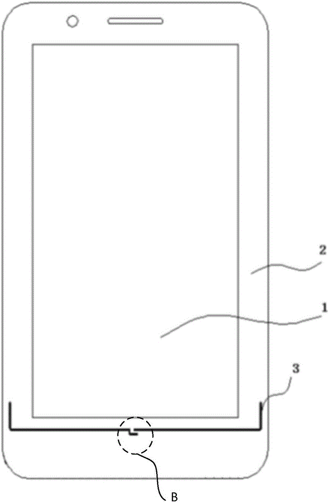
[0061] This embodiment provides a wiring method for a sensor of a touch screen, such as figure 1 As shown, the touch screen includes a display area, and the wiring method includes:
[0062] Step 101, use the ground wire of the sensor below the display area as a first ground wire, and disconnect the first ground wire.
[0063] Wherein, the touch screen can be a capacitive touch screen, and the capacitive touch screen can be applied to terminals such as mobile phones and tablet computers. Taking a mobile phone as an example, the display area 1, the frame 2, and the first ground line 3 of the touch screen on the mobile phone are as follows: figure 2 As shown in , the disconnected position of the first ground wire 3 is shown in reference sign B. Usually, the entire ground wire of the sensor will be laid around the display area of the mobile phone, and the ground wire below the display area will be affected by the wiring method of the sensor used for the touch screen in the pri...
Embodiment 2
[0069] Such as Figure 3-4 As shown, the difference between this embodiment and Embodiment 1 is that the touch screen further includes an antenna clearance area located below the display area, the first ground line includes a first ground line segment and a second ground line segment, and the first ground line segment Two ground wire segments are connected to the first ground wire segment, and the wiring method also includes:
[0070] Step 102, when the sensing module of the sensor is located outside the antenna clearance zone, arranging the first ground wire outside the antenna clearance zone;
[0071] or,
[0072] Step 103, when the sensing module of the sensor has an overlapping area with the antenna clear area, arrange the first ground line segment to cover the outer edge of the overlapping area, and arrange the second ground line segment at the outer edge of the overlapping area. outside the above antenna clearance zone. The shape after wrapping depends on the actual s...
Embodiment 3
[0078] Such as Figure 7 As shown, the difference between this embodiment and Embodiment 2 is that: the driving signal line of the sensor includes a first driving signal line segment and a second driving signal line segment, and the second driving signal line segment is connected to the first driving signal line segment , after the operation performed when the induction module and the antenna clearance area have an overlapping area in step 103, the wiring method further includes:
[0079] Step 104, when the sensing module of the sensor has an overlapping area with the antenna clear area, arranging the first driving signal line segment to be connected to the outer edge of the non-overlapping area of the sensing module;
[0080] The non-overlapping area is an area of the sensing module outside the clear area of the antenna.
[0081] Step 105 , extending and arranging the second driving signal line segment in a direction away from the headroom area of the antenna. Its e...
PUM
 Abstract
Description
Claims
Application Information
 - R&D Engineer
- R&D Manager
- IP Professional
- Industry Leading Data Capabilities
- Powerful AI technology
- Patent DNA Extraction
Browse by: Latest US Patents, China's latest patents, Technical Efficacy Thesaurus, Application Domain, Technology Topic, Popular Technical Reports.
© 2024 PatSnap. All rights reserved.Legal|Privacy policy|Modern Slavery Act Transparency Statement|Sitemap|About US| Contact US: help@patsnap.com


