


Quick Research
Generate reliable direction feasibility study reports for your R&D in just a few steps.

Technical Q&A
Discover and master advanced knowledge NOW. Basics, ideas, possibilities, all at once.

Find Solutions
As an expert in R&D theories, this can generate solutions to your technical problems instantly.

Evaluate Feasibility
Analyze your overall solution with one click, know your potential R&D risks in advance.

Monitor Landscape
Get weekly tech updates, stay abreast of the latest tech innovations and key insights.
Unequal-speed impeller mechanism and compressor and expansion mechanism including same
A technology of expansion mechanism and impeller, applied in the direction of machine/engine, blade supporting element, mechanical equipment, etc., can solve the problems of unreasonable structure, inability to solve multi-level linkage, limited application and so on
- Summary
- Abstract
- Description
- Claims
- Application Information
AI Technical Summary
Problems solved by technology
Method used
Image

Examples
Embodiment 1
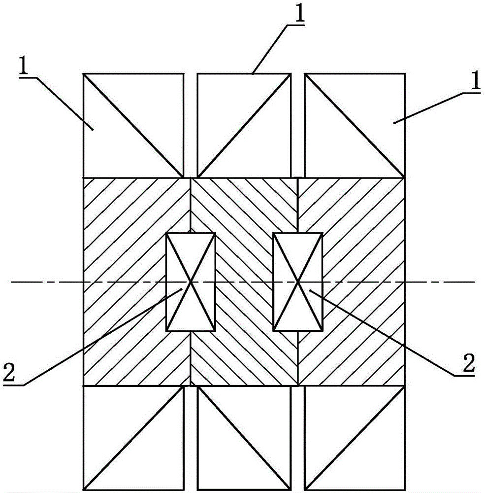
[0073] Such as figure 1 The variable-speed impeller mechanism shown includes three impellers 1 , and the three impellers 1 are arranged correspondingly in sequence, and two adjacent impellers 1 are set in linkage through the transmission device 2 .
[0074] See attached figure 1 , when including more than two corresponding impellers 1 in sequence, the transmission device 2 can be arranged between each group of adjacent impellers 1, so as to conveniently realize multi-stage linkage, and at the same time realize each of the The rotating speed of the impeller 1 is not equal to improve the performance of the impeller.
[0075] In this embodiment, three correspondingly arranged impellers 1 are provided. As a convertible embodiment, the number of impellers 1 included in the different-speed impeller mechanism can be set according to actual needs. When it includes three or more The impeller 1 can be as figure 1 As shown, all the impellers 1 are arranged correspondingly in sequence,...
Embodiment 2
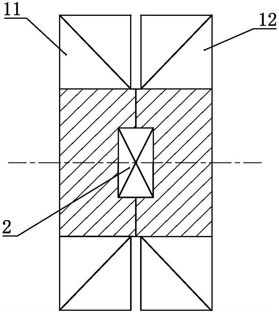
[0077] Such as figure 2 The difference between the variable speed impeller mechanism shown in Embodiment 1 is that the variable speed impeller mechanism includes two impellers 1, which are respectively set as the moving impeller A 11 and the moving impeller B 12, and the moving impeller A 11 Correspondingly arranged with the moving impeller B 12 to form a working stage, the moving impeller A 11 and the moving impeller B 12 are directly set in linkage through the transmission device 2 .
[0078] As an alternative embodiment, the moving impeller A 11 and the moving impeller B 12 can also be set in linkage indirectly through the transmission device 2, for example, between the moving impeller A 11 and the transmission device 2 or in the Another transmission mechanism is also arranged between the moving impeller B 12 and the transmission device 2 .
Embodiment 3
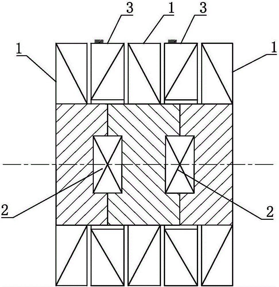
[0080] Such as image 3 In the shown variable speed impeller mechanism, on the basis of Embodiment 1, the speed change device 2 is set as a forward speed change device so that the two impellers 1 that are set in linkage through it rotate in the same direction. A stationary impeller 3 is arranged between the two impellers 1 set in linkage with the speed changer.
[0081] As an alternative implementation manner, the stationary impeller 3 in this embodiment may not be provided.
[0082] As a changeable embodiment, the speed change device 2 can also be changed to a reverse speed change device so that the rotation directions of the two impellers 1 set in linkage are opposite. At this time, the stationary impeller 3 does not need to be provided. .
PUM
 Abstract
Description
Claims
Application Information
 - R&D Engineer
- R&D Manager
- IP Professional
- Industry Leading Data Capabilities
- Powerful AI technology
- Patent DNA Extraction
Browse by: Latest US Patents, China's latest patents, Technical Efficacy Thesaurus, Application Domain, Technology Topic, Popular Technical Reports.
© 2024 PatSnap. All rights reserved.Legal|Privacy policy|Modern Slavery Act Transparency Statement|Sitemap|About US| Contact US: help@patsnap.com