
Air duct installation component

A technology for installing components and air ducts, which is applied to household appliances, applications, and display cabinets, etc., can solve the problems of affecting assembly efficiency, single structure, and large gaps in the assembly of the box, saving manpower, improving assembly efficiency, and installing Simple and convenient steps

Active Publication Date: 2016-09-07
HEFEI HUALING CO LTD +1
View PDF7 Cites 0 Cited by
  • Summary
  • Abstract
  • Description
  • Claims
  • Application Information

AI Technical Summary

Problems solved by technology

[0002] At present, the air ducts of commercial display cabinets on the market are mostly injection-molded parts with a single structure. One air duct structure is designed for each model, which has poor versatility.
Moreover, the structural design of the air duct is simple, there are many screws fixed on the front, and the assembly gap with the tank is large, which is not beautiful. In addition, because the box is large and high, it is necessary to drag the heavy air duct to the hole to install, which affects the assembly efficiency

Method used


Image

  • Air duct installation component
  • Air duct installation component
  • Air duct installation component

Examples


Embodiment 1

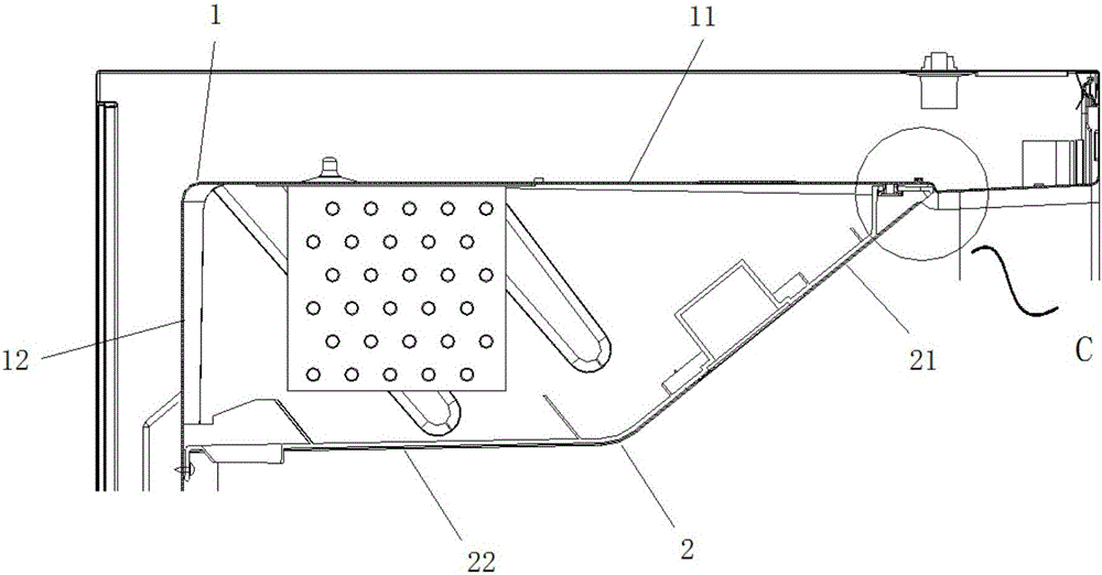
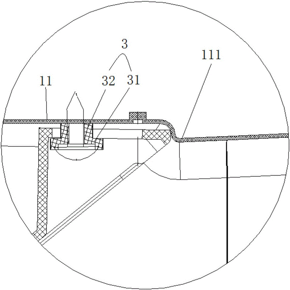
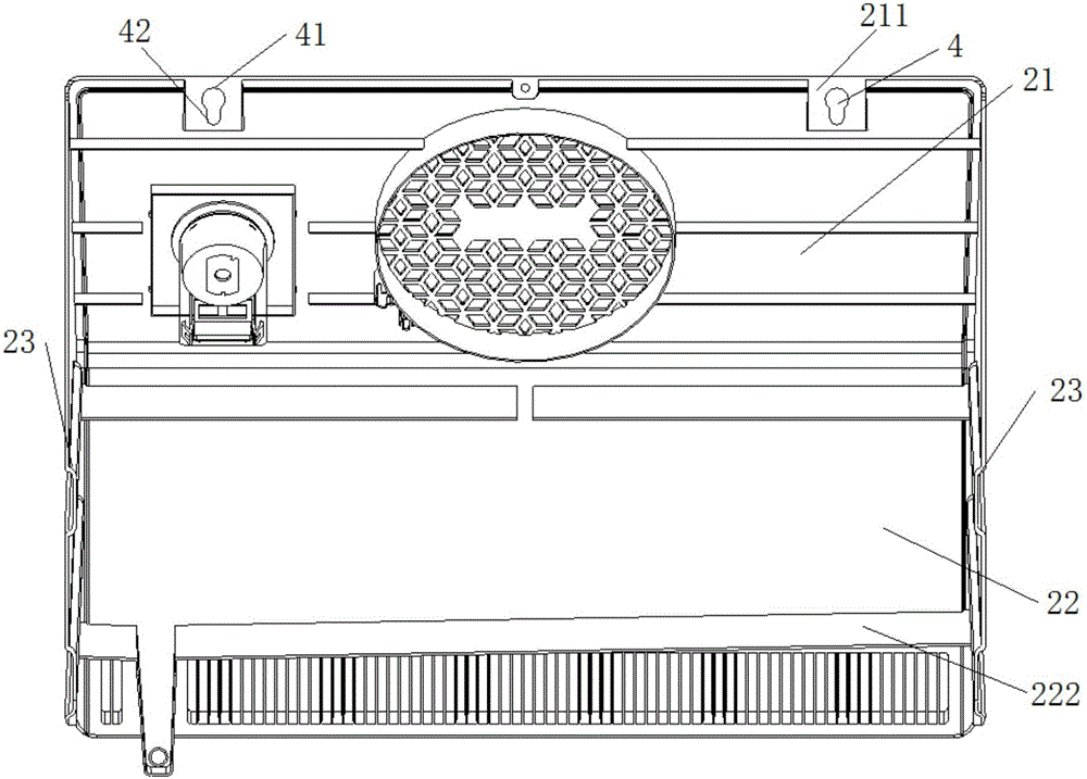
[0055] like Figure 1-9 As shown, an air duct installation assembly is arranged inside the box body, including a box inner liner 1 and an air duct housing 2 connected to the box inner liner 1, the air duct housing 2 is connected with the top surface 11 of the box liner and a side surface 12 of the box liner to form an air duct, the air duct shell 2 includes an integrally formed inclined panel 21, a bottom wall 22 and two side walls 23, the The inclined panel 21 has a common side with the bottom wall 22 and the two side walls 23; the edge of the inclined panel 21 is provided with at least two connecting plates 211 parallel to the bottom wall, and each connecting plate 211 is provided with A connection hole 4 . At least two connecting pieces 3 are provided at the positions where the top surface 11 of the tank liner matches the connecting holes 4 , and the connecting holes 4 correspond to the connecting pieces 3 one by one and are snap-connected. The connecting piece is directl...

Embodiment 2

[0061] like Figure 1-9 As shown, an air duct installation assembly is arranged inside the box body, including a box inner liner 1 and an air duct housing 2 connected to the box inner liner 1, the air duct housing 2 is connected with the top surface 11 of the tank inner tank and a side surface 12 of the tank inner tank to form an air duct, the air duct housing 2 is provided with at least two connection holes 4, the top surface 11 of the tank inner tank is connected to the At least two connecting pieces 3 are provided at matching positions of the connecting holes 4 , and the connecting holes 4 correspond to the connecting pieces 3 one-to-one and are snap-connected. The central axis of the connecting piece is provided with a through hole, and the bolt passes through the through hole and is connected with the top surface of the tank inner tank by threads, or the top surface of the tank inner tank is also provided with a bolt hole correspondingly. The bolts pass through the throu...


PUM


Abstract

The invention provides an air duct installation component. The air duct installation component is arranged in a box body, and comprises a box body inner liner and an air duct shell connected with the box body inner liner; the box body inner liner is provided with a top surface of the box body inner liner, and a side face of the box body inner liner connected with the top surface of the box body inner liner; an air duct is formed by connecting the air duct shell with the top surface of the box body inner liner and the side face of the box body inner liner; at least two connecting holes are formed in the position, close to the end, of the air duct shell; the top surface of the box body inner liner is provided with at least two connecting pieces at the positions matched with the connecting holes; the connecting holes and the connecting pieces correspond to each other one by one and are in clamping connection with each other in a detachable way. The air duct installation component has the beneficial effects that the front end of the air duct shell is fixed by means of the clamping connection between the connecting holes and the connecting pieces arranged on the top surface of the box body inner liner, so that the installation steps are simple and convenient, and the phenomenon that the heavier air duct needs to be dragged to be aligned with a mounting hole for installation when being connected by bolts in the traditional way is avoided; therefore, the manpower is saved, and the assembly efficiency is improved.

Description

technical field [0001] The invention relates to the field of household appliance accessories, in particular to an air duct installation component. Background technique [0002] At present, the air ducts of commercial display cabinets on the market are mostly injection-molded parts with a single structure, and one air duct structure is designed for each model, which has poor versatility. Moreover, the structural design of the air duct is simple, there are many screws fixed on the front, and the assembly gap with the tank is large, which is not beautiful. In addition, due to the large and high box body, it is necessary to drag the heavy air duct to the hole for installation, which affects the assembly efficiency. Contents of the invention [0003] The technical problem to be solved by the present invention is to provide an air duct installation component with good versatility, convenient installation and beautiful appearance. [0004] The technical scheme that the present i...

Claims


Application Information

Patent Timeline
Patent Type & Authority Applications(China)
IPC IPC(8): A47F3/04
CPCA47F3/04
Inventor 汪洁翔桑贤起姬忠文
Owner HEFEI HUALING CO LTD
Learn More