
Organic light emitting display panel and driving method therefor

A technology of light-emitting display and driving method, which is applied to static indicators, instruments, etc., which can solve the problems of stealthy lighting of organic light-emitting diode D and the inability to ensure that the potential of the second node Q2 is written into the ideal potential, so as to solve the problem of uneven display Effect

Active Publication Date: 2016-08-31
WUHAN TIANMA MICRO ELECTRONICS CO LTD +1
View PDF5 Cites 36 Cited by
  • Summary
  • Abstract
  • Description
  • Claims
  • Application Information

AI Technical Summary

Problems solved by technology

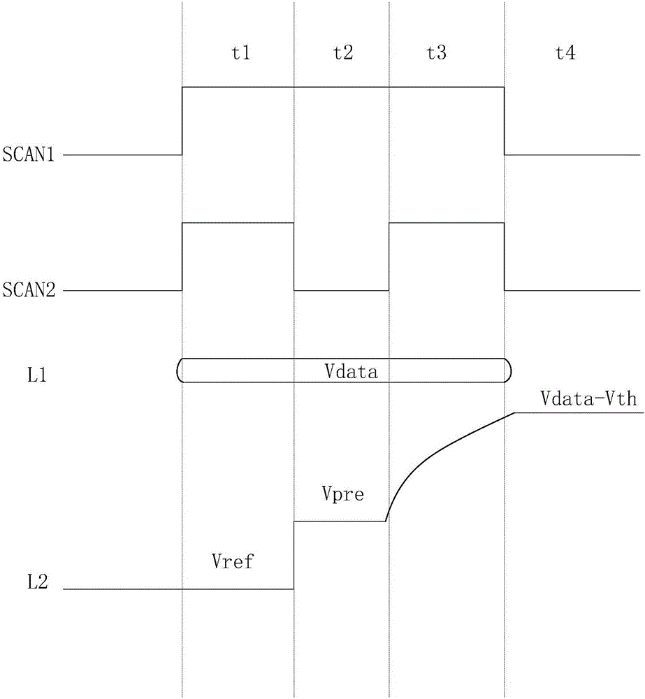
[0011] but, Figure 1A During the process of threshold value compensation by the external compensation circuit shown in the figure, at the moment t1 and t2, due to the conduction of the second transistor T2, there will be a problem that the organic light emitting diode D steals light; At this time, the potentials are respectively written into the first node Q1 and the second node Q2. Since the second transistor T2 is turned on due to the potential of the first node Q1 at this time, the electrical signal input by the first constant voltage source VDD passes through the second transistor T2 It is transmitted to the second node Q2, that is, at this moment, the potential signal of the first constant voltage source VDD and Vref are written into the second node Q2 at the same time, so it cannot be guaranteed that the potential of the second node Q2 is written into an ideal potential

Method used


Image

  • Organic light emitting display panel and driving method therefor
  • Organic light emitting display panel and driving method therefor
  • Organic light emitting display panel and driving method therefor

Examples


Embodiment Construction

[0030] In order to make the above objects, features and advantages of the present invention more comprehensible, the present invention will be further described below in conjunction with the accompanying drawings and embodiments.

[0031] It should be noted that in the following description, specific details are set forth in order to fully understand the present invention. However, the present invention can be implemented in many other ways than those described here, and those skilled in the art can make similar extensions without departing from the connotation of the present invention. Accordingly, the present invention is not limited to the specific embodiments disclosed below.

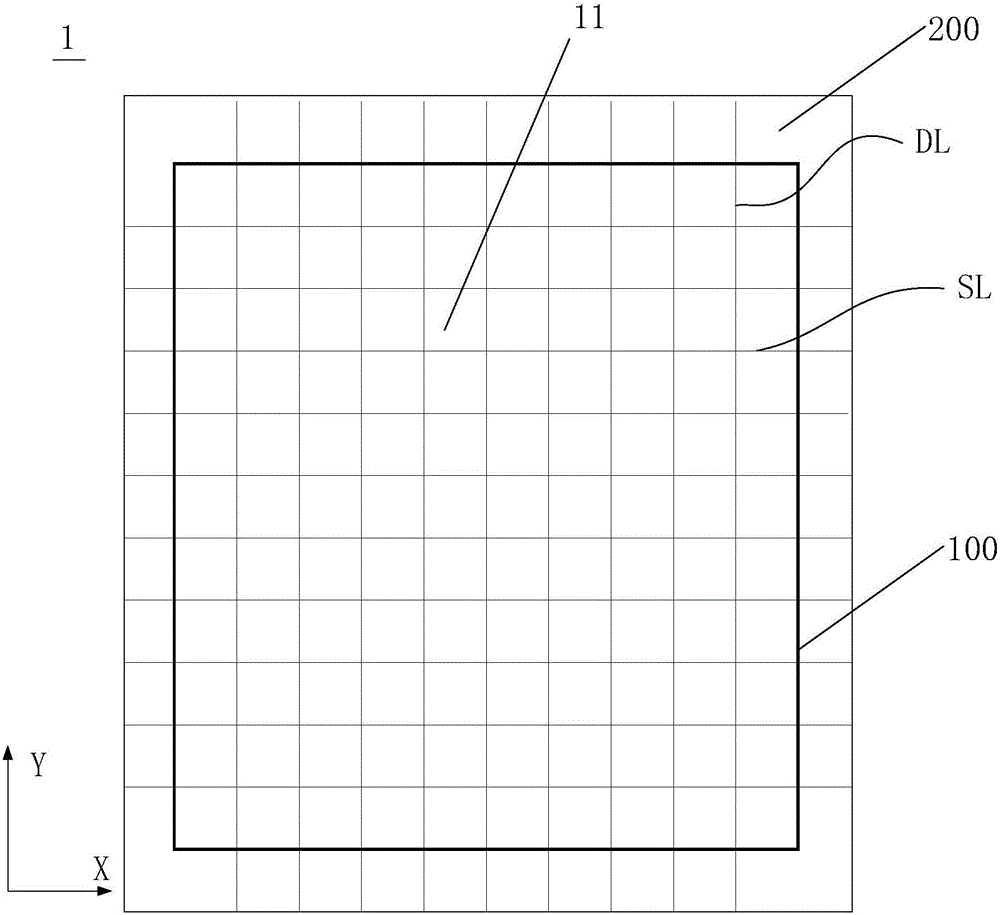
[0032] Figure 2A It is an organic light emitting display panel provided by an embodiment of the present invention. Such as Figure 2A As shown, the organic light emitting display panel 1 includes a display area 100 and a non-display area 200, wherein the display area 100 includes a plurality of ...


PUM


Abstract

The invention describes an organic light emitting display panel and a driving method therefor. The organic light emitting display panel comprises at least one first circuit and a plurality of second circuits; the first circuit comprises a signal generating unit, a signal input control unit and a signal detecting unit. Each second circuit comprises a first transistor. The first circuit is connected with the second circuits via data cables, and the first circuit is used for capturing and compensating threshold value of the first transistor of each second circuit. The organic light emitting display panel and the driving method therefor can effectively solve problems that display is not uniform due to threshold voltage shift, an organic light emitting diode is still turned on stealthily during threshold value compensation processes, and node electric potential cannot be accurately written in during the threshold value compensation processes.

Description

technical field [0001] The invention relates to the display field, in particular to an organic light emitting display panel and a driving method thereof. Background technique [0002] In recent years, various light-weight and small-sized flat panel display devices have been developed instead of cathode ray tubes. Examples of these flat panel display devices include liquid crystal display panels, plasma display panels, and electroluminescence display panels. Among them, the electroluminescent display panel realizes the normal display of the display panel through the electroluminescent device in the display panel. According to the different materials of the light-emitting layer, the electroluminescent device is divided into two types: inorganic light-emitting and organic light-emitting. Response speed, high luminous efficiency, strong brightness, and wide viewing angle are called the new generation display technology in the industry. [0003] As a current-controlled light-em...

Claims


Application Information

Patent Timeline
Patent Type & Authority Applications(China)
IPC IPC(8): G09G3/3208
CPCG09G3/3208
Inventor 吴桐邹文晖李玥钱栋刘刚朱仁远向东旭
Owner WUHAN TIANMA MICRO ELECTRONICS CO LTD
Learn More