
Moving sliding table

A sliding table, sliding platform technology, applied in the direction of machine gear/transmission mechanism testing, measuring devices, instruments, etc., can solve problems such as low motion accuracy

Inactive Publication Date: 2016-08-31
JIANGSU LANLING ELECTROMECHANICAL TECH CO LTD
View PDF5 Cites 8 Cited by
  • Summary
  • Abstract
  • Description
  • Claims
  • Application Information

AI Technical Summary

Problems solved by technology

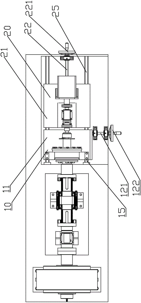
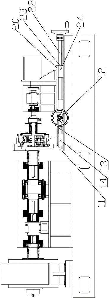
[0007] According to the technical solution provided by the embodiment of the present application, by setting the gear rack on the first sliding platform to mesh with the gear, the rotation of the gear is converted into the linear motion of the rack, and the rotation of the lead screw is converted into the linear motion of the nut, which is convenient for controlling the fixed gear. The linear motion distance between the first sliding platform of the rack and the second sliding platform fixed with nuts can solve the problem of low motion accuracy of the existing sliding platform relying on manual push

Method used


Image

  • Moving sliding table
  • Moving sliding table

Examples


Embodiment Construction

[0011] The application will be further described in detail below in conjunction with the accompanying drawings and embodiments. It should be understood that the specific embodiments described here are only used to explain related inventions, rather than to limit the invention. It should also be noted that, for ease of description, only parts related to the invention are shown in the drawings.

[0012] It should be noted that, in the case of no conflict, the embodiments in the present application and the features in the embodiments can be combined with each other. The present application will be described in detail below with reference to the accompanying drawings and embodiments.

[0013] Please refer to figure 1 and figure 2 , the mobile sliding table of the present invention comprises a first sliding device 10 and a second sliding device 20, the first sliding device 10 is provided with a first sliding platform 11 and a gear 13, and the gear 13 is fixed on the frame by a ...


PUM


Abstract

The invention discloses a moving sliding table which comprises a first sliding device and a second sliding device, wherein a first sliding platform and a gear are arranged on the first sliding device; the gear is fixed on a frame through a central shaft; a rack is arranged on the first sliding platform; the rack is meshed with the gear; a second sliding platform is arranged on the second sliding device; a screw nut pair is arranged on the second sliding platform; the screw nut pair comprises a screw rod and a nut; the nut is fixed on the second sliding platform; and the screw rod is fixed on the frame. As the rack is arranged on the first sliding platform and is meshed with the gear, the rotation of the gear is converted into the linear motion of the rack, the rotation of the screw rod is converted into the linear motion of the nut, the distance of the linear motion of the first sliding platform fixed with the rack and the second sliding platform fixed with the nut can be conveniently controlled, and the problem of low motion precision of the existing sliding platform due to manual driving is solved.

Description

technical field [0001] The present disclosure generally relates to the field of test devices, in particular to the field of test devices for transmission performance of reducers, and in particular to a mobile slide table. Background technique [0002] There are two main types of joint reducers currently used in the field of robotics: one is the RV reducer and the other is the harmonic reducer. In the articulated robot, the RV reducer belongs to the cycloid precision reducer, which has high rigidity and rotation accuracy. In the design of the robot, the RV reducer is generally placed at the heavy load position of the boom and the frame, and the harmonic deceleration The reducer is placed on the waist and hand of the forearm. The motion accuracy and performance of the reducer at all robot joints directly affect the overall working performance and service life of the industrial robot. [0003] With the rapid development of modern industry, the degree of production automation i...

Claims


Application Information

Patent Timeline
IPC IPC(8): G01M13/02
CPCG01M13/025
Inventor 顾耸智薛永贵
Owner JIANGSU LANLING ELECTROMECHANICAL TECH CO LTD
Learn More