Range-extending electric hybrid generator and engine crankshaft connecting device

A coupling device and generator technology, applied in the direction of machines/engines, electromechanical devices, electric components, etc., can solve problems such as belt slippage, accelerated bearing wear, and crankshaft power output shaft fracture, etc., to achieve a reasonable and stable overall structure design The effect of work

Active Publication Date: 2016-08-31
河南东啟新能源车业有限公司
View PDF5 Cites 3 Cited by
  • Summary
  • Abstract
  • Description
  • Claims
  • Application Information

AI Technical Summary

Problems solved by technology

[0002] The existing generator and engine crankshaft connection devices generally have the following forms: (1) The generator is located on the side of the engine, and the power output shaft of the engine is equipped with a pulley, which is connected with the drive shaft of the generator through a belt. It is characterized by easy installation, The disadvantage is that it is bulky, and it is not suitable to be arranged in a small structural space, and the belt is easy to slip; (2) the rotor of the generator is directly installed on the power output shaft of the engine crankshaft, and the stator is connected to the casing of the engine through the connection plate of the generator. The diameter bearing capacity of the power output shaft of the engine crankshaft with this structure should be greater than or equal to the bearing capacity required for the operation of the generator rotor, and the operation of the generator depends on the bearing capacity of the crankshaft. The advantages of this structure are small size and low manufacturing cost; the disadvantages Due to the limitations of the engine structure, the power of the engine is large, the power output shaft of the crankshaft is thin, and the power output shaft of the crankshaft can meet the torque required by the generator, but cannot meet the bearing capacity of the generator, the structure cannot be used; Affected by the structure of the engine and generator itself, when the installation distance between the generator rotor and the engine crankshaft bearing is remote, it is necessary to install the generator bearing on the power output shaft of the engine crankshaft close to the generator to meet the requirements of the generator. However, after adding the generator bearing, how to ensure the concentricity between the generator bearing and the two crank bearings at three points and a line has become a technical problem that needs to be solved in the industry. In addition, the diameter of the power output shaft of the engine crankshaft If the generator shaft is too small to meet the operating capacity of the generator rotor, it is necessary to increase the generator shaft. When the generator shaft is enlarged, a new connection method must be adopted between the generator shaft and the power output shaft of the engine crankshaft.
[0003] In the manufacturing technology of the engine case and the crankshaft, the left and right case of the engine position the engine crankshaft through bearings to form two fulcrums, and the generator shaft relies on the bearings to form a third fulcrum, which is connected with the engine connecting plate. Engine case connection, during the processing and installation of the engine case and the generator connection plate, within the allowable tolerance range, the coaxiality of the generator shaft and the engine crankshaft will still have a tolerance of 0~40 wires. Corresponding technical measures, the concentricity deviation of the crankshaft bearing and the generator bearing at three points and one line will lead to accelerated wear of the bearing and fracture of the power output shaft of the crankshaft during the operation of the engine, forming serious technical defects, so it is necessary to design A generator and engine crankshaft connection device with stable quality and long service life, meeting the technical requirements of range-extended generators

Method used


Image

  • Range-extending electric hybrid generator and engine crankshaft connecting device
  • Range-extending electric hybrid generator and engine crankshaft connecting device
  • Range-extending electric hybrid generator and engine crankshaft connecting device

Examples


Embodiment Construction

[0022] The specific implementation manners of the present invention will be described in detail below in conjunction with the accompanying drawings.

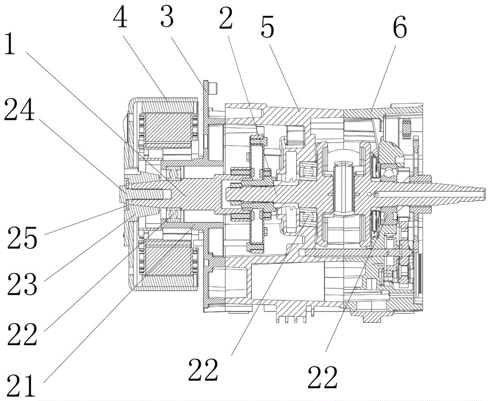
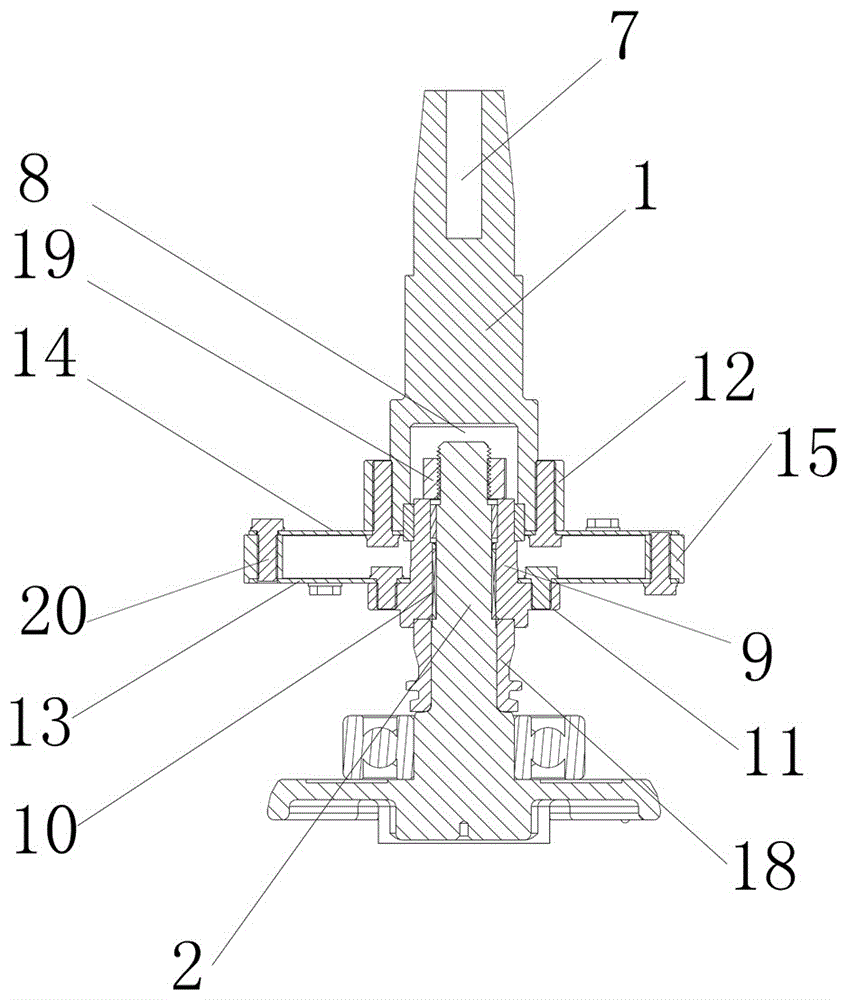
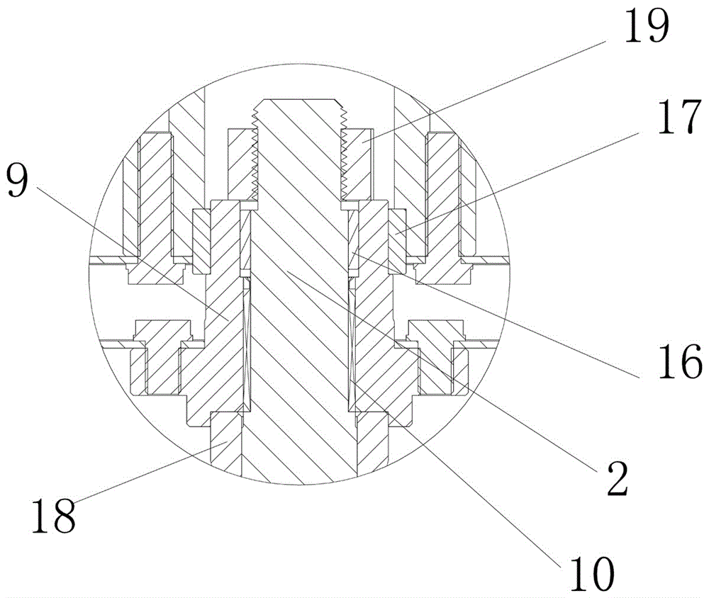
[0023] see Figure 1-Figure 3 , a coupling device between an extended-range electric hybrid generator and an engine crankshaft, comprising a generator shaft 1, an engine crankshaft 2, a generator connecting plate 3 and a generator rotor 4 corresponding to the generator shaft 1, and a generator rotor 4 corresponding to the engine crankshaft 2 The left box body 5 and the right box body 6 are set, and the left box body 5, the right box body 6 and the generator connection plate 3 are fixedly connected, and the support sleeve 21 is arranged in the generator connection plate, and the support sleeve A locating bearing 22 is arranged between the pipe 21 and the generator shaft, and a locating bearing is also arranged between the left casing and the right casing and the crankshaft of the engine.

[0024] The upper part of the generator ...


PUM


Abstract

The invention relates to the technical field of electric hybrid automobile generators. A range-extending electric hybrid generator and engine crankshaft connecting device is characterized in that an assembly sediment tank is axially arranged on the bottom part of a generator shaft; a connecting sleeve is arranged on the upper part of an engine crankshaft in a sleeving way, and is in mesh connection with the engine crankshaft through splines; the upper end of the connecting sleeve is matched and arranged in the assembly sediment tank in a sleeving way; connecting sleeve flanges are arranged on the bottom part of the connecting sleeve; generator shaft flanges are arranged on the bottom part of the generator shaft; a stress unloading assembly is arranged between the connecting sleeve flanges and the generator shaft flanges, and comprises a lower connecting plate, an upper connecting plate, and backing rings arranged between the lower connecting plate and the upper connecting plate. The range-extending electric hybrid generator and engine crankshaft connecting device provided by the invention is reasonable in integral structure design; with the structure, the generator shaft is thickened and a generator bearing is enlarged under the condition that the engine crankshaft is thinner, so that the bearing requirement of generator rotor running is fully met, and the service life of the generator bearing is prolonged.

Description

technical field [0001] The invention relates to the technical field of electric hybrid vehicle generators, in particular to a coupling device between a range-extended electric hybrid generator and an engine crankshaft. Background technique [0002] The existing generator and engine crankshaft connection devices generally have the following forms: (1) The generator is located on the side of the engine, and the power output shaft of the engine is equipped with a pulley, which is connected with the drive shaft of the generator through a belt. It is characterized by easy installation, The disadvantage is that it is bulky, and it is not suitable to be arranged in a small structural space, and the belt is easy to slip; (2) the rotor of the generator is directly installed on the power output shaft of the engine crankshaft, and the stator is connected to the casing of the engine through the connection plate of the generator. The diameter bearing capacity of the power output shaft of...

Claims


Application Information

Patent Timeline
IPC IPC(8): F02B63/04H02K7/18
CPCF02B63/042H02K7/1807
Inventor 韩群山马延昌
Owner 河南东啟新能源车业有限公司
Why Eureka
Try Eureka